Do You Need to Worry About a Solar Simulator’s Light Collimation or Angle of Emission?
Light from the Sun travels a very long distance before reaching the Earth, and as a result most of the light rays are close to parallel to one another (with a maximum angle of about 0.5 degrees ).
We call such parallel light rays collimated. If light rays are not parallel to one another, we say they’re uncollimated.
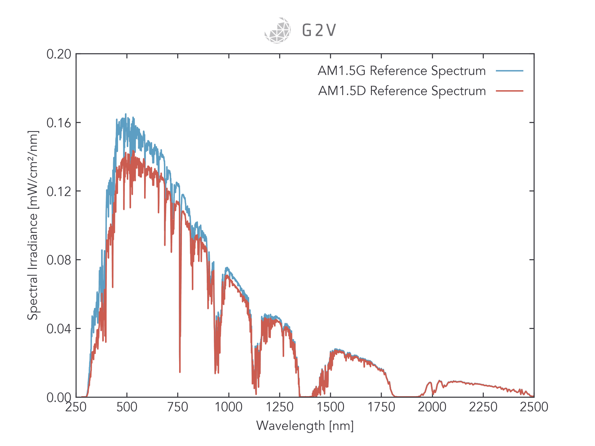
Most of the sunlight we receive is directed light, meaning that it comes from the Sun to a position on the ground without scattering or reflecting. While there is some light from scattering and reflection sources, it is a small portion of total sunlight, as we can see in the plot below comparing AM1.5G (global, which includes direct and indirect sunlight) and AM1.5D (direct only).
Because most sunlight is direct, that means most of it is collimated.
While sunlight is mostly collimated, the output of most solar simulators is not necessarily collimated, and there is no collimation requirement in the solar simulation standards. Part of the reason for this omission is because the sensitivity to collimation really depends on the application and geometry you’re trying to illuminate.
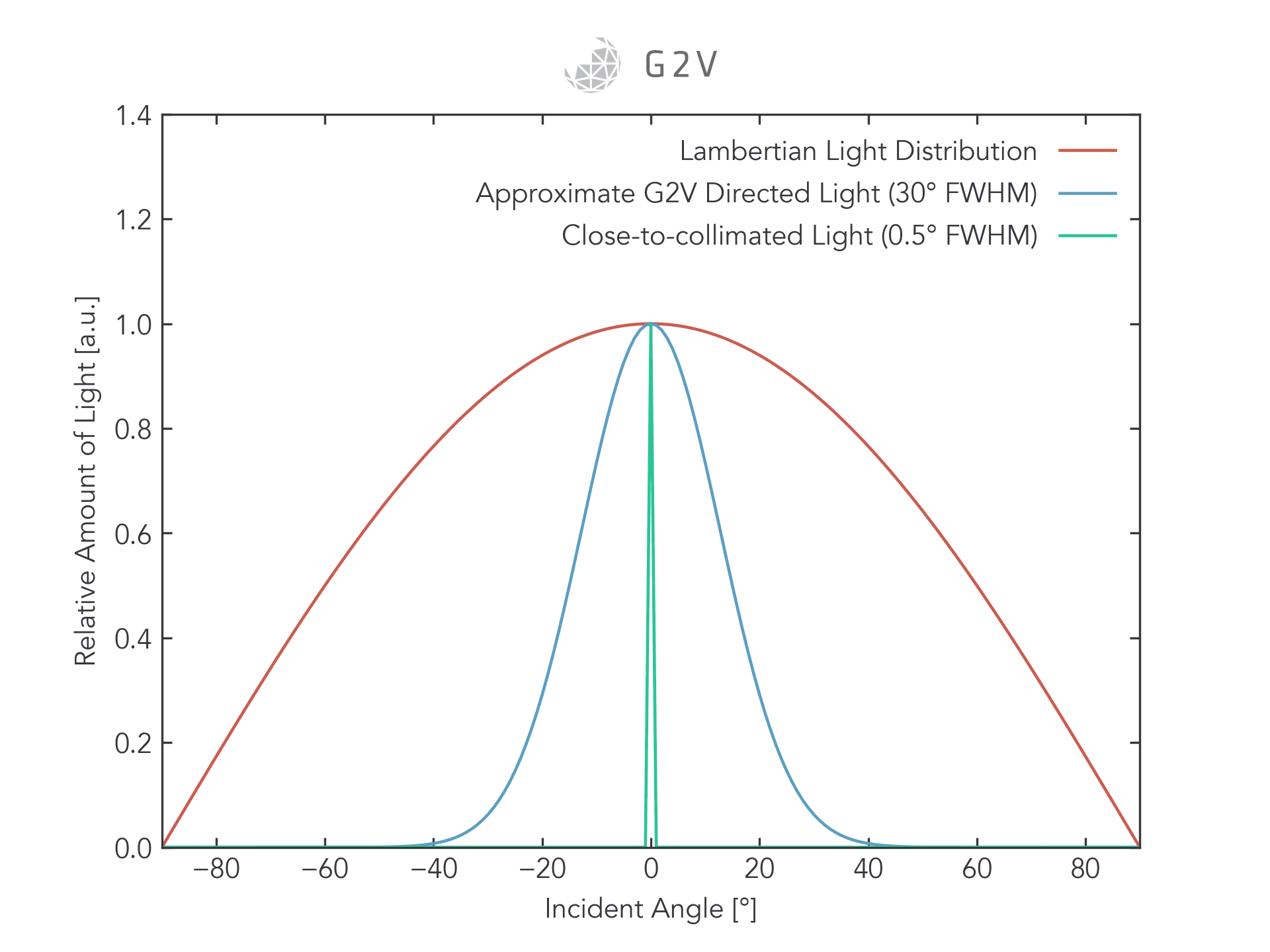
G2V’s solar simulators have varying degrees of collimation. The Lambertian Pico model, for example, has a Lambertian angular distribution, meaning that the emitted light intensity varies with the cosine of the incident light angle. Most LEDs emit Lambertian light, which is far from collimated, as we can see in the plot below.
G2V’s directed solar simulator models have angular distributions that are approximately Gaussian with a full-width at half maximum (FWHM) between 20 to 40 degrees.
The difference between Lambertian, directed, and collimated light is shown in the figure below.
For many applications, this difference of angular distribution is not important to the underlying principles being investigated, and so it can be ignored as long as the other solar simulator parameters (spectral match, spatial uniformity and temporal stability) meet requirements.
However, there are some applications where the angular distribution of light matters a great deal, and it’s important to be aware of these cases so you can get a solar simulator that will adequately reproduce the effects you’re trying to study.
Situations Where You May Require a Collimated Light Source
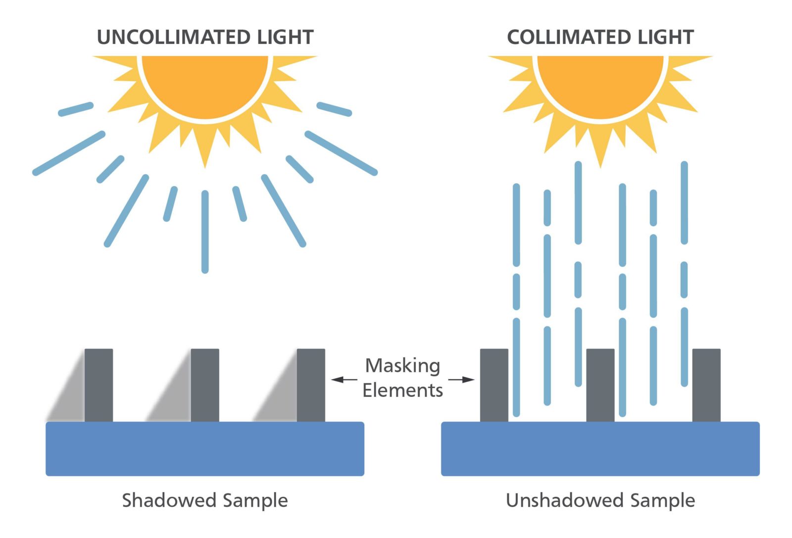
If you’re illuminating a sample with cavities, the angular content of your light source will matter a great deal, as an uncollimated light source will lead to shadowing that doesn’t occur under real sunlight. This concept is shown in the figure below.
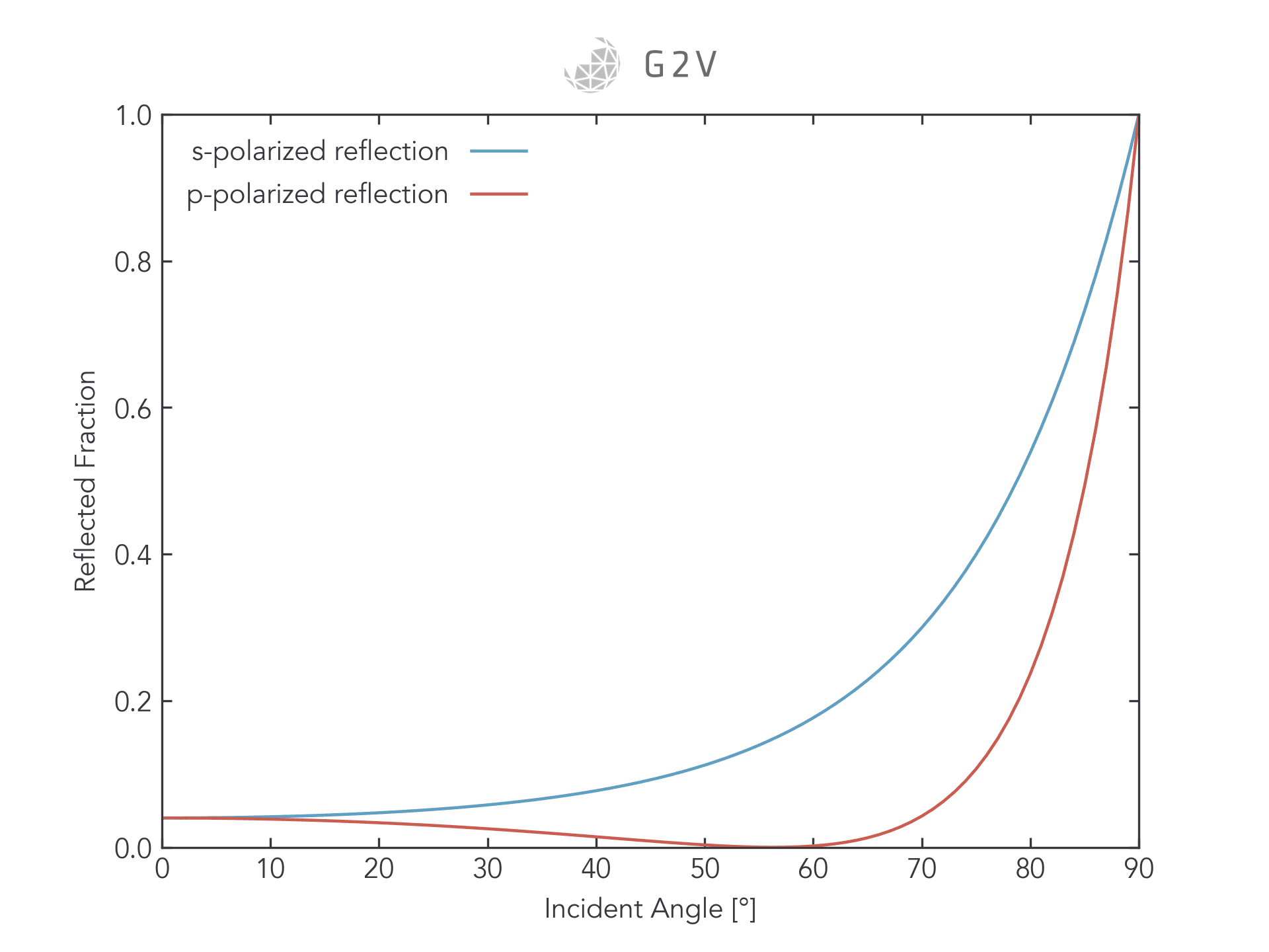
Another concept that may influence the need for collimated light is that of Fresnel reflection , which occurs whenever light strikes an interface between two materials. As you can see from the plot below, the magnitude of reflected light increases as the incident angle increases. If your incident light has a significant angular component, then a significant portion of it may simply be reflected, which is something that wouldn’t happen to the same extent under collimated sunlight.
Another situation where collimated light might be needed is for a Sun sensor or star tracker. If you’re trying to calibrate a detector to measure the direction of the Sun or a star within a few degrees of precision, then you’ll likely need a solar simulator that emits collimated light whose divergence is smaller than the precision required.
There may be ways around the angular distribution of the light source. In the shadowing example given above, if you have a reference cell you can mount under the same shadowed conditions, then you may be able to increase your solar simulator’s intensity until you get the required unshadowed intensity on your reference cell, and then use that compensated intensity for all your tests.
If, however, you’re trying to study the angular dependence of a material’s behaviour or response to light, then it’s likely that you need a collimated solar simulator to fully reproduce realistic behaviour.
Match Your Light’s Angular Emission to Your Experiment’s Angular Acceptance
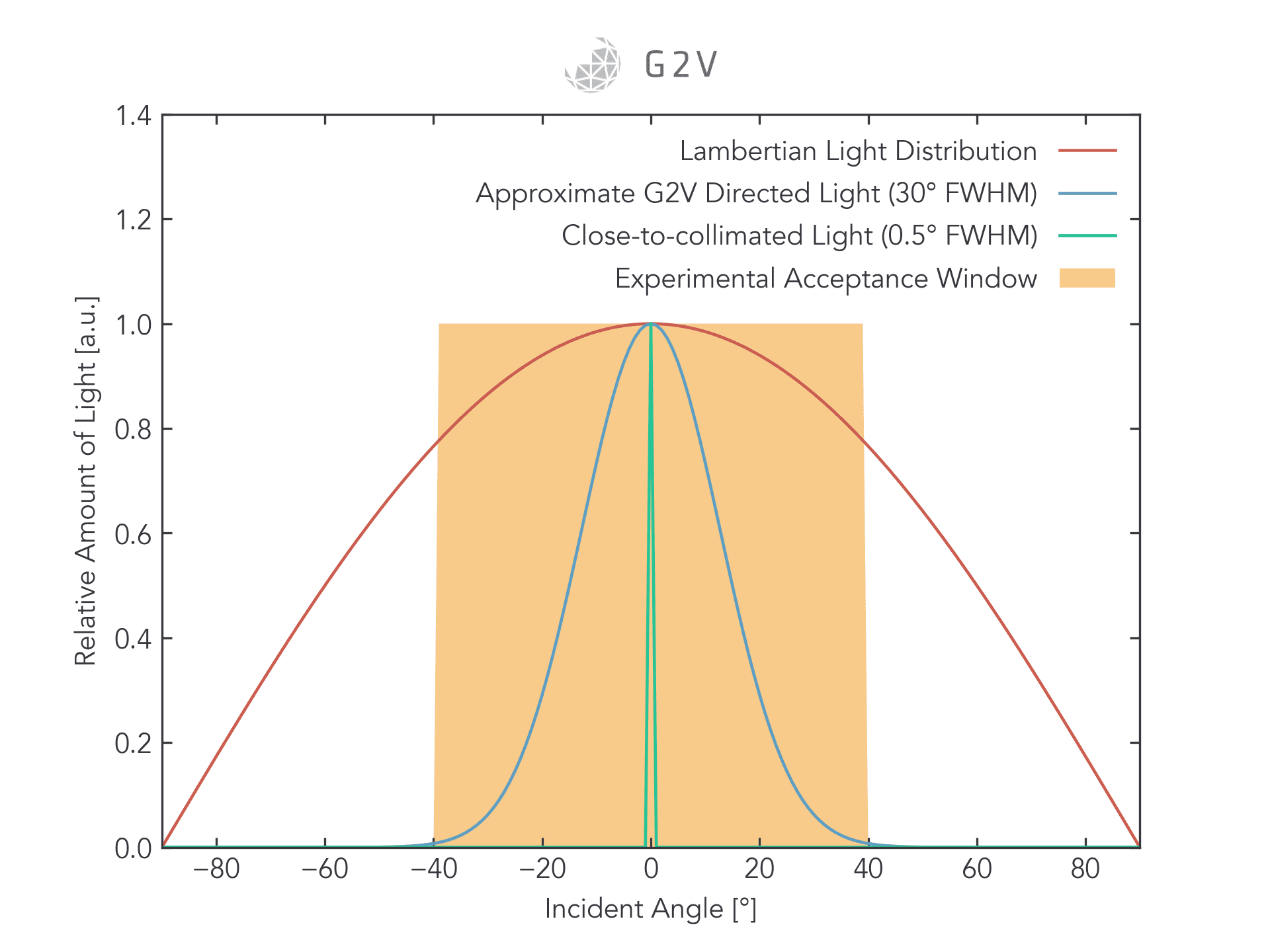
Another way to look at the problem is in terms of the angular acceptance of your experiment. If your experiment can accept and be independent of a wide range of angles, then any solar simulator that produces light within that range of angles will do the job, as shown in the figure below.
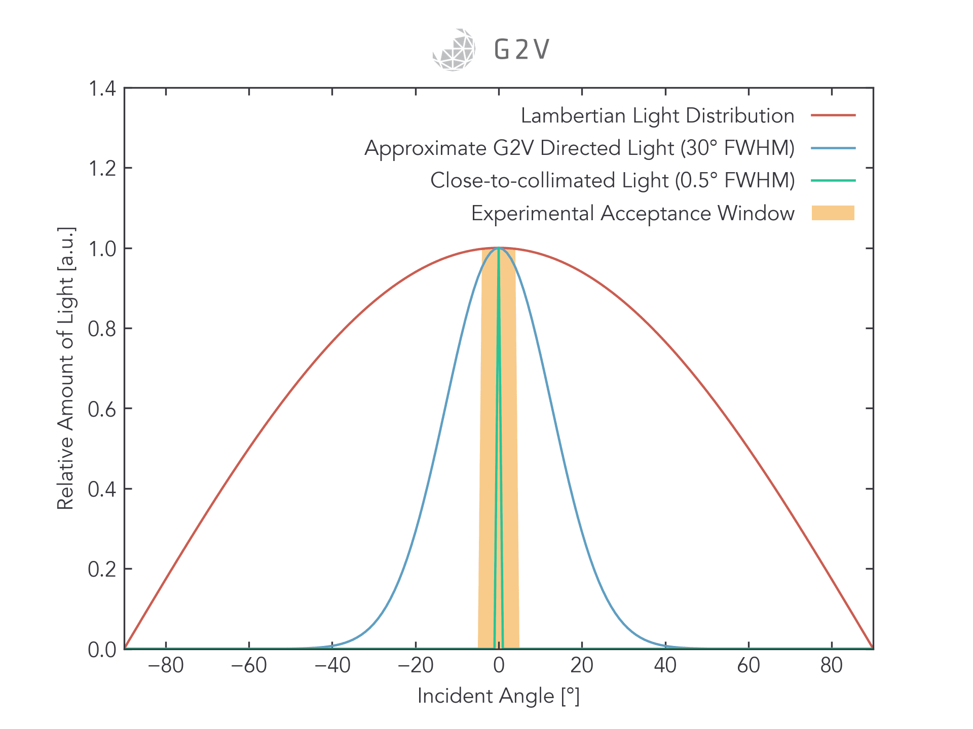
If, on the other hand, your experiment only accepts a narrow range of angles (or your experiment’s behaviour drastically changes outside that angular range), then you will have to find a solar simulator whose emission is within that range.
We hope this explanation helps clarify some of the cases where angular emission of a solar simulator can mean the difference between accurate and inaccurate results.
Regardless of your application, angular sensitivity of your target phenomenon/phenomena is an important parameter to consider to ensure your light source matches your testing needs.
If you have any questions more specific to your use case(s), please contact us to discuss with our engineering team who has experience carrying out a wide variety of photonic testing.