What is a Photodetector?
At a high level, a photodetector is any device that captures light from across the entire solar spectrum or segments of the UV, visible, or IR regions. The mechanisms they detect may differ, as may the units of measure they produce.
Photodetector Devices Qualification and Solar Simulators
The exact method(s) to use for the qualification of photodetectors vary depending on the application, but we’ll try to cover some aspects to consider for the most common ones, including cameras, hyperspectral & sun sensors, solar cells, photodiodes and LiDAR.
First of all, regardless of the application, it’s important to be aware of the seven key parameters of a solar simulator and how they can affect the device’s results.
The three primary criteria covered by the solar simulator IEC 60904-9:2020 standards are spectral match, spatial uniformity, and temporal stability. This criterion is how solar simulators are classified as Class AAA, BBC, or other.
The next two parameters are spectral coverage and spectral deviation, which refer to how much of a target spectrum is covered by a solar simulator and the total error at all wavelengths, respectively.
The last two parameters that need to be considered are uniform volume and angular distribution, which we’ll discuss more below. This article is organized according to the parameters to consider, and examples of assessment and impact on different applications will be discussed along the way.
If you are already up to date on the IEC standards and understand your light requirements to qualify your photodetectors, head over and check out our Class AAA tunable solar simulators.
If not, let’s bring you up to speed on qualifying photodetectors!
How Do Solar Simulator Standards Affect Photodetector Qualification?
Photodetector Spectral Range and A Solar Simulator Spectral Coverage

When we look at photodetectors, they generally select portions of the entire solar spectrum to be measured. The same is true for the output of a solar simulator. For example, if you are testing a visible wavelength camera, your photodetector may only register light from 400 nm to 700 nm. When selecting a solar simulator, you will want to select one to the range that covers your required photodetector range. In most cases, having an exact spectral coverage of a solar simulator that matches the spectral range of a photodetector isn’t possible. The solar simulator will often exceed the photodetector range, which isn’t an issue. More importantly, having an accurate spectral match in the area your photodetector is reading matters.
This is where the Class A spectral match comes into play. Here are a few examples that will elaborate on this point.
If you are testing a hyperspectral camera, you may need to have a solar spectrum that extends into the infrared, and exactly how far will be specific to your device. Therefore, for your application, you should scrutinize spectral matches only in the areas of your device’s responsibility to maximize the accuracy of the device’s results. Or if you try to have it perform as close to real-world light conditions, the device will see.
A second example is a silicon solar cell’s responsivity range. Depending on the type of cell, such as a single-junction or a multi-junction, the requirement in the device range will vary. Again, much like our hyperspectral camera example, a light source that matches what you’re trying to test is imperative.
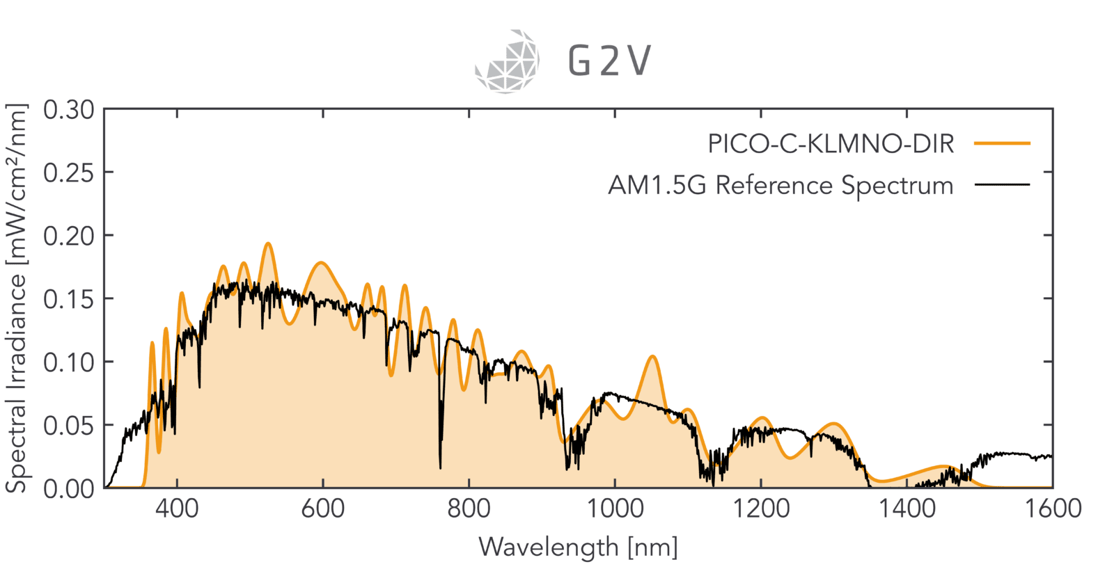
Take a look at these two spectrums below. The first graph is a hypothetical spectrum that is a Class A spectral match by the IEC standards definition but is not indicative of real-world conditions. Compare this to the second Class A spectral match LED solar simulator from G2V. Notice the closer match to the spectrum.
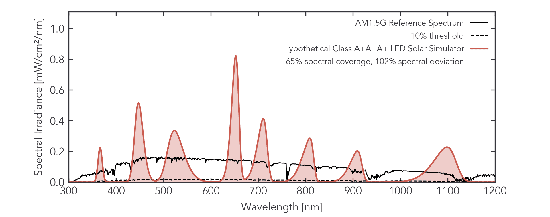
Closely related to the spectral match are spectral coverage and deviation. As mentioned above, you only really need to worry about spectral coverage in the responsivity regions of your photodetector, and a similar principle applies to spectral deviation. If your photodetector is insensitive to changes in irradiance over a given spectral bin, then you may be able to relax your spectral deviation requirements, for example. If, on the other hand, your photodetector has many narrow spectral bins that dictate its response, then you’ll likely want to ensure that you not only have good spectral coverage of these bins, but that the deviation is low for all of them as well.
Spectral Tunability
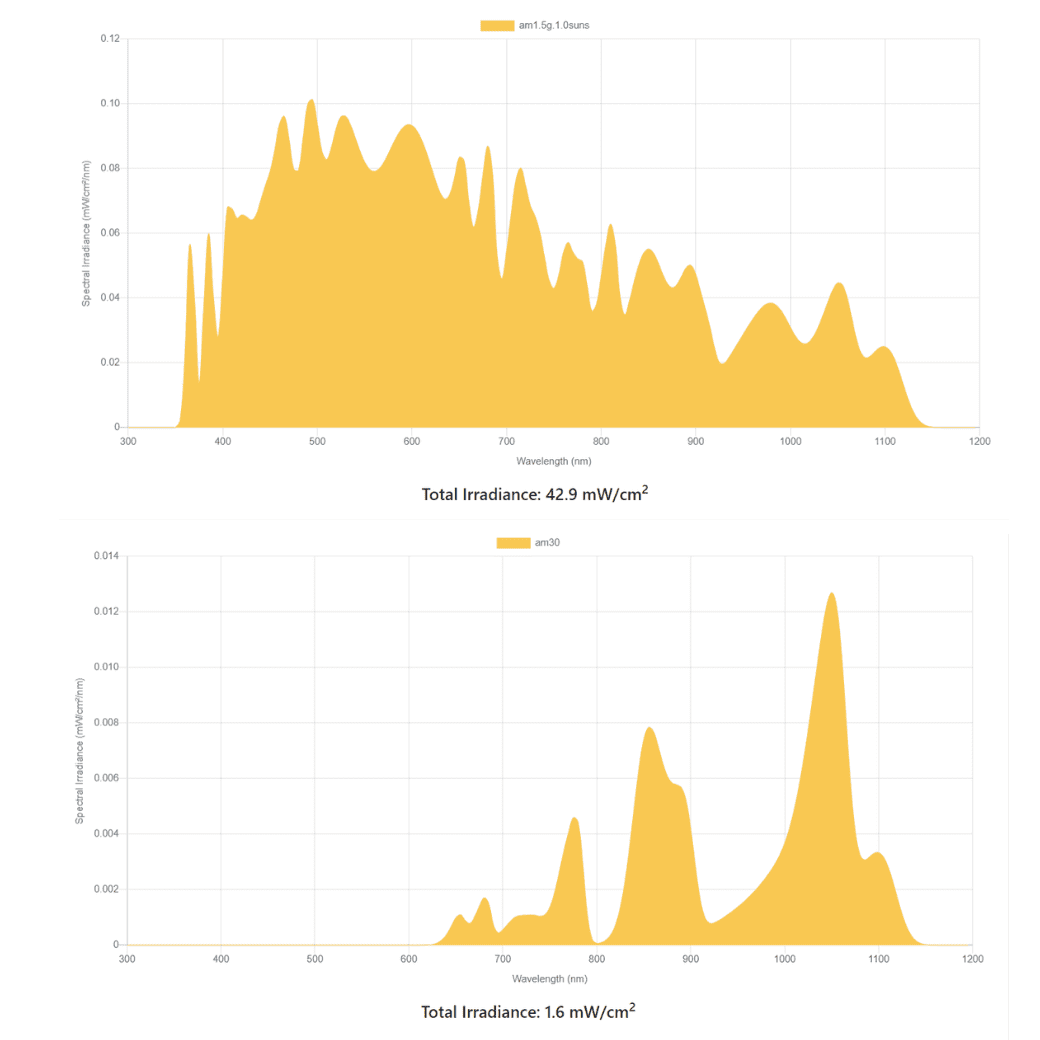
It would be great if the device you are testing only had one condition to which it would be exposed. Let’s be serious: Any device you are qualifying for operating worldwide will see various solar spectrums over the day, month, and year. This is where the other spectral aspect worth considering, which is not listed in the IEC standards, is tunability.
More specifically, whether or not you’d like to tune the spectrum to assess your device’s sensitivity to different wavelength bands, here are a few questions you could answer using a tunable solar simulator.
What is the impact of green-light glare on your camera’s image quality?
How does afternoon sunlight on a remote sensor affect the noise picked up on LiDAR throughout the day?
A solar simulator tuning specific spectral regions may greatly facilitate the necessary tests. Tuning individual channels can, for example, allow a camera developer to assess cross-channel interference by comparing the RGB channel responsivity of full-spectrum light against the responsivity of individually active wavelength channels.
Spatial Uniformity of a Photodetector

Spatial uniformity may determine the error bars on your device’s qualification if, for example, you’re trying to calibrate a camera’s pixel-to-pixel variation across an illuminated area. Depending on the area you’re trying to qualify, you may need to know more specific information about the resolution of the spatial uniformity measurements for a given solar simulator. Clarifying with the solar simulator manufacturer is important because a Class A uniformity solar simulator with measurements every 2.5 cm over a wide plane differs from one where the measurements were only made every 10 cm. Knowing the degree to which you need to assess your device’s spatial sensitivity and making sure your solar simulator’s output matches those requirements or at least meets them part way is important in optical detector qualification under artificial sunlight.
Uniform Volume Considerations
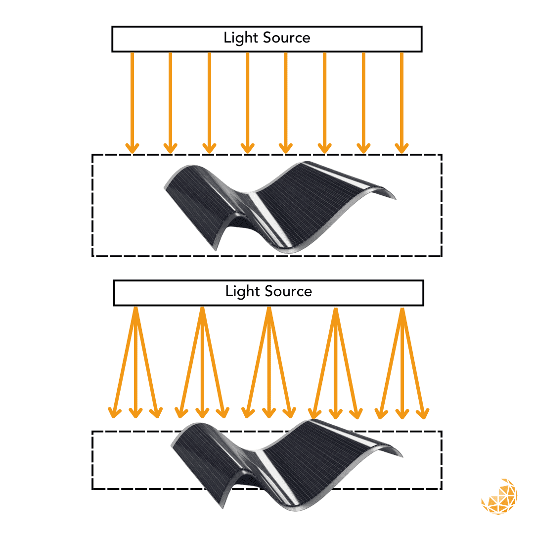
This aspect of uniformity is not often mentioned but is vital when testing non-planar devices. Since most solar simulators rarely produce perfectly collimated light, the intensity and spatial uniformity of the irradiance field will change as a function of working distance. In other words, the brightness will likely decrease, and the field won’t have the same uniform area as the farther you move away from the light source. We refer to this uniform area and the distance over which it is maintained as “uniform volume” because it is a 3-dimensional space where tests can be carried out confidently. In practice, this means ensuring your device falls within the uniform volume or is coplanar with the solar simulator manufacturer’s recommended working plane. This is usually trivial if your device under test (DUT) is planar. If your DUT is non-planar, you’ll need to know the dimensions of a solar simulator’s uniform volume.
Ensuring your tolerance for intensity and uniformity changes are aligned with a solar simulator’s performance changes with distance is key to achieving desired results.
Temporal Stability Considerations
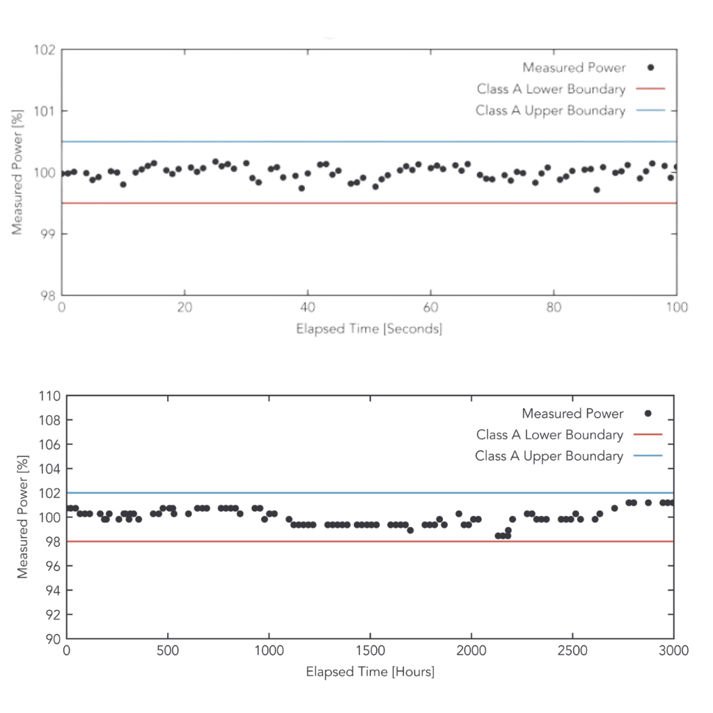
Temporal stability is usually the most straightforward parameter for a solar simulator to achieve, but some optical detector validation might have more exacting requirements. If you want to automate testing or test intermittent behaviour by shuttering or turning the lights on and off, you want to ensure the shutter’s opening, light warmup, and/or automated turn-on is of a shorter duration than the behaviour you’re trying to assess. For example, if you want to qualify solar cells on a production line, knowing how quickly the solar simulator can turn on accurately is essential to determining the fastest allowable throughput. If you’re trying to simulate sun blockages or rapid attenuation changes on a satellite’s sun tracker, you’ll again want to know that the solar simulator’s ability to change is representative of the phenomena you’re trying to investigate.
Considerations of the Angular Distribution of Light
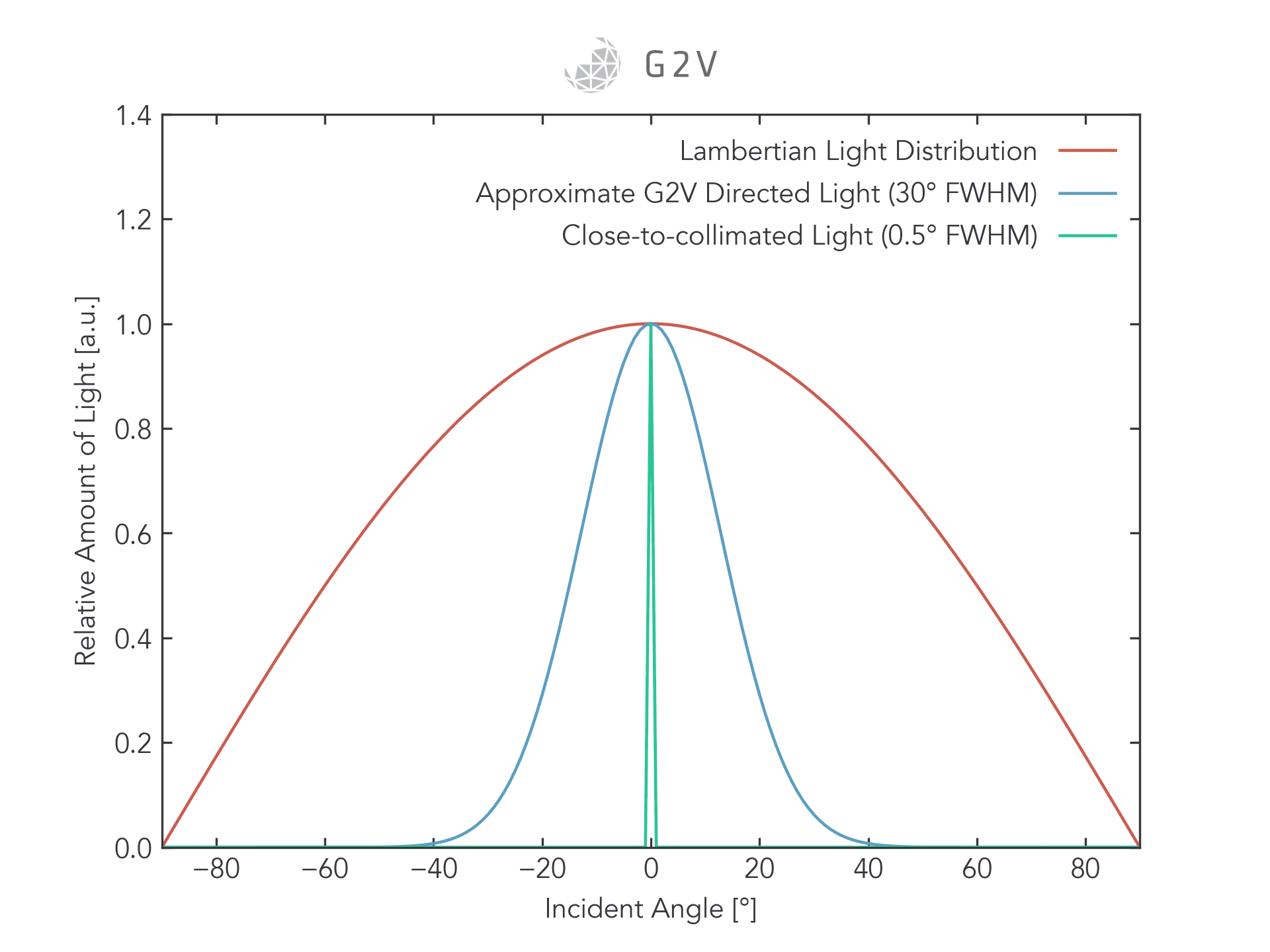
Sunlight is mostly collimated, i.e. its rays are parallel to one another. Solar simulators, on the other hand, are rarely perfectly collimated. For many optical devices, this difference is unimportant. For example, a solar cell’s current and voltage performance won’t be affected by the angular content of the incident light — it will still convert photons to electron-hole pairs and undergo the same processes.
In other applications, however, the angular distribution of light will matter a great deal. In sun sensors or star trackers which need to determine the sun’s direction to within a few degrees of precision, a solar simulator may require light that’s as close to collimated as possible, with a divergence no larger than the desired precision of the sun sensor. For UAV remote sensing applications trying to assess the impact of the sun’s angle on gathered images, the incident angle of light may also be important, and require more stringent collimation.
The angular distribution of light is a bit tricky to understand, so we have an entire article describing angle of emission. In the end, it’s most important to ensure that the solar simulator’s angular content meets the needs of what you’re trying to investigate for your photodetector.
Summary
There were many considerations to keep in mind. The key thing to understand is that a solar simulator is an indispensable instrument for researchers around the world to repeatedly produce light in laboratory conditions. If you are looking for a Class AAA Tunable solar simulator that hits these requirements, head over to our solar simulator products page for more information or to request a quote!
Photodetector Validation Using A Solar Simulator – TLDR
Solar simulators can add significant value for the validation of optical sensors that are impacted by interference from or that are dependent on sunlight. Before starting, it’s essential to:
- Match the solar simulator’s spectral output (including spectral match, spectral coverage and spectral deviation) to the spectral sensitivity of your device(s)
- Ensure the uniformity of illumination will give you the error bars you’re seeking in spatial qualification
- Ensure the intensity drop-off and uniformity changes as a function of distance (i.e. the “uniform volume”) will be able to accommodate your target device(s)
- Ensure the time constants of the solar simulator’s operation, including shutters, warm-up and any automation, will allow you to test the time-varying phenomena of interest.
- Match the solar simulator’s angular distribution of light to the angular sensitivity of your device or application