
You’ve accidentally left a pair of sandals in your backyard or on your porch, and when you finally realize they’re there months later, the sandals are sun-bleached and brittle.
You visit a used car lot and see that the black upholstery on the vehicles on the periphery, soaking in sunlight all day long, is a much lighter colour than that of the vehicles shaded beneath a carport. The very old vehicles have visible rust and paint chips.
Many of us have witnessed first-hand the effects of weathering and exposure to the elements.
Weathering and material degradation can become even more extreme as you move away from the Earth’s surface.
Aircraft and spacecraft are exposed to the jet stream, more extreme temperatures, and more intense particle fluxes and radiation fluxes from the sun. Can you imagine seeing an airplane wing turn sun-bleached and brittle in-flight?
You don’t want to find out a material’s unsuitable for flight when you’re 20,000 ft in the air. Or, worse yet, in the vacuum of space.
You need to test materials on the ground, often following the mantra, “Test as you fly.” Materials should be put through the expected conditions, ideally before investing large sums to launch them beyond the stratosphere. However, reproducing the conditions in space can be challenging in Earth-based laboratories.
The Role Solar Simulators Play in Testing
Solar simulators can play a major role in aerospace materials testing, by accurately reproducing the radiation environments experienced by an aircraft or spacecraft in flight. This allows for early identification of material degradation pathways.
Solar-simulator-accelerated degradation testing can be achieved using intensities greater than one sun so a material’s lifetime estimate doesn’t require twenty-five years of field testing.
Field-exposure tests for determining service lifetimes are too slow for most manufacturers.
Solar simulators can provide aerospace materials scientists and spacecraft manufacturers with the test data they need to make improvements and innovations for safer, longer-lifetime materials.
In this article, we’ll discuss how solar simulators aid in better aerospace materials testing, why this testing is important, and what solar simulator features are most useful for this application.
Solar Simulators Allow For More Careful Photochemical Reaction Monitoring
Photochemists and material researchers are often interested in fully understanding and quantifying the reaction and degradation pathways of a material of interest.
For aerospace material degradation, a common pathway is often photodestruction because of the high energies of UV light.
Below, we’ll go through an example derivation of photodegradation reaction equations and rates reproduced from H. Cottin et al.’s 2008 paper entitled “Heterogeneous solid/gas chemistry of organic compounds related to comets, meteorites, Titan, and Mars: Laboratory and in lower Earth orbit experiments.” This example serves well to illustrate a key problem faced by researchers in this field.
The chemical reaction for photodegradation can be written as follows:
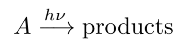
Where A is a molecule, hv indicates exposure to light, and the products are known fragments of A. The rate of this photolysis chemical reaction is often described by the following equation:
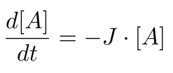
Where [A] is the number density of the reagent A, and J is the destruction cross-section of the molecule.
Integrating this equation gives
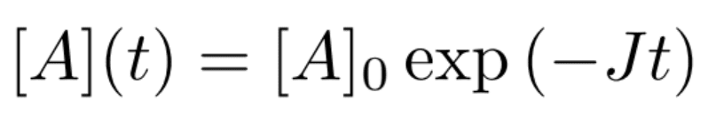
Finally, J is experimentally determined by measuring the concentration of A as a function of time, then plotting the following equation for slope determination:
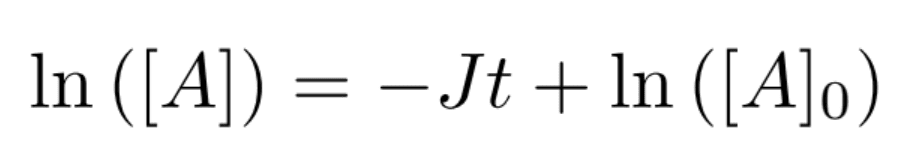
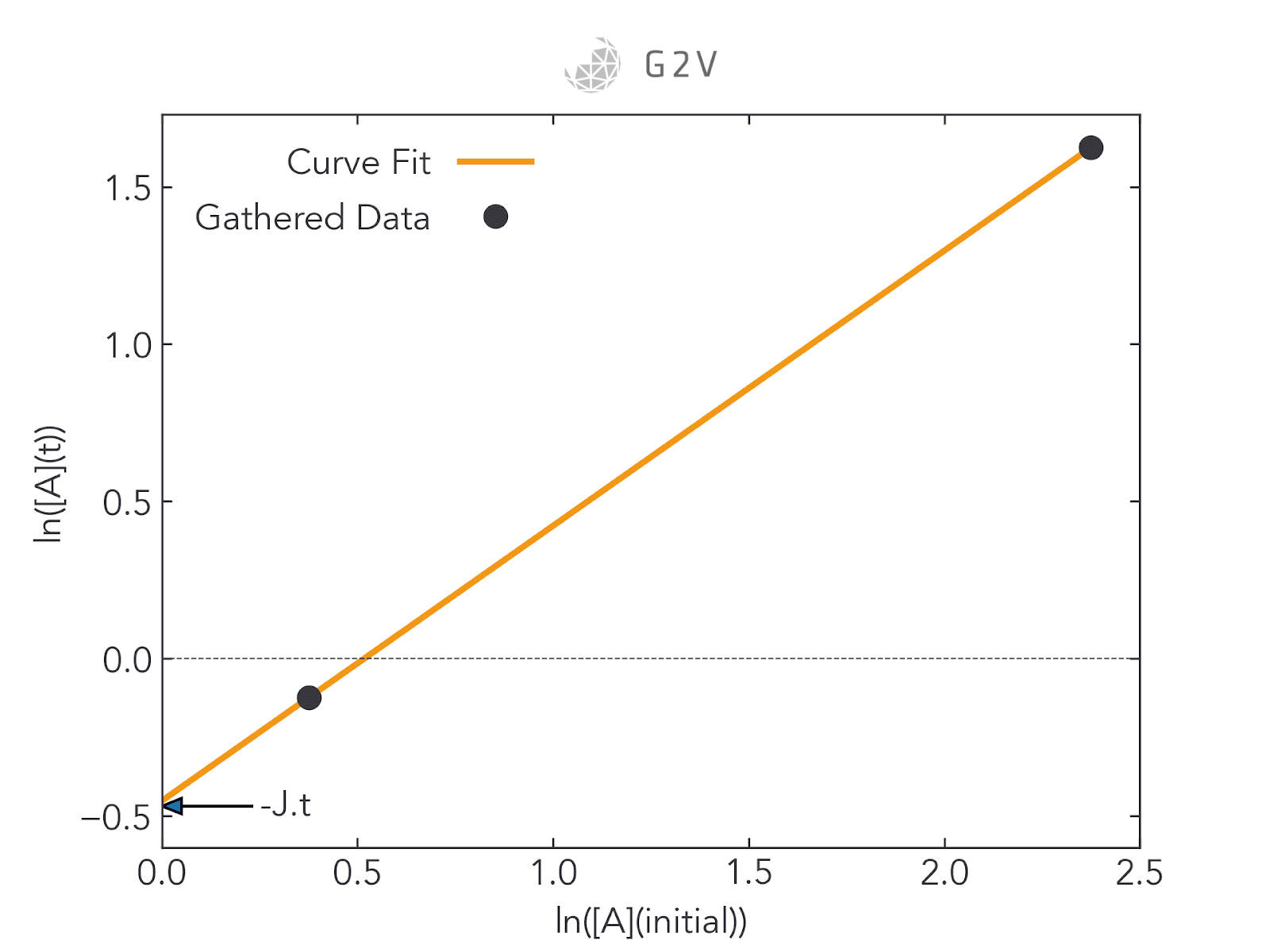
When this study can be done in the laboratory, getting sufficient data for good curve-fitting is relatively straightforward, as we can see in the rightmost figure below. In space, however, researchers are often restricted to two data points (as shown in the leftmost figure below): one for the initial concentration of A (at t=0), and one for the final concentration of A when a sample or vessel returns to the ground (at the experiment’s end time). Curve-fitting a two-point plot is highly inaccurate.
Here is where ground testing can be so valuable. By providing laboratory access to the materials that are being exposed to adverse conditions, researchers are able to collect more data for intermediate concentrations and therefore more accurately assess photodegradation rates. This greater data collection ultimately improves a researcher’s confidence in their understanding of a material’s behaviour under the expected conditions.
However, as we’ll discuss throughout this article, reproducing outer space conditions in a laboratory setting can be quite challenging. Materials not only have to contend with higher-intensity sunlight and UV exposure, but the bombardment of charged particles, cosmic radiation, and more — a collection of environmental factors known as space weather, which we’ll discuss next.
Space Weather’s Effect on Materials
As soon as you travel beyond the Earth’s atmosphere, you lose the protection of our atmospheric layers (including ozone) as well as the protection of the Earth’s magnetic field for charged particles.
You experience the full gamut of radiation of both solar and galactic origin.
Cosmic radiation in our solar system is made up of protons, electrons, alpha-particles and heavy ions.
Our sun’s solar wind eruptions are made up of up to 95% protons, alpha-particles and heavy ions. These particles have a major impact on material lifetimes in space, and ground-based tests often seek to combine charged particle testing with electromagnetic radiation tests.
Since this article focuses on the value that solar simulators can provide for testing spacecraft materials, we will focus our discussion on electromagnetic radiation rather than the effects of space weather.
Solar simulators can (and are) combined with other material tests including the effects of temperature, vacuum, and charged particle bombardment mentioned above.
For example, one chamber can be used to photolyze samples at the appropriate temperature for space, while a separate chamber can put samples under vacuum to investigate the impact of vacuum-pressure. However, it is difficult to execute simultaneous testing of all these stress parameters, not to mention energetic particle irradiance at the correct intensities.
NASA’s Marshall Space Flight Center (MSFC) is one unique facility capable of providing a variety of charged particles for reproducing space environmental conditions in concert with electromagnetic radiation.
However, this is a very elaborate, world-class facility that many aerospace developers may not be able to access. Therefore it’s likely that exposure facilities in space may still be required.
Nevertheless, there is still much information to gain from solar-radiation testing on the ground, and the rest of this article will focus on such applications.
Aerosols Accelerating Aircraft Degradation
Corrosion resistance is a standard test in weathering.
Traditionally, this is done by spraying different salt aerosols (usually sodium chloride, NaCl) into a fog inside a weathering chamber, as specified by ISO 9227 (Corrosion Tests in Artificial Atmospheres; Salt Spray Tests) and ASTM B117-03 (Standard Practice for Operating Salt Spray (Fog) Apparatus).
Salt isn’t the only aerosol that impacts aircraft lifetime. Researchers have shown that sulfuric acid can shorten an aircraft’s service lifetime by 40-50%. Such sulfuric acid is produced by volcanic eruptions which, although infrequent, have a major impact on aviation for several years thereafter. The 1991 Mount Pinatubo eruption in the Philippines was one such event which sparked a major investigation by aviation researchers into material degradation pathways.
It is therefore important to include aerosol testing in aerospace material evaluations. Such testing can include sodium chloride, sulfuric acid, other salts, ozone and other pollutants, with only minor variations to test chamber setup.
While this is another significant factor for aerospace material research, we’ll focus our further discussion on electromagnetic radiation testing.
Aerospace Material Exposure to UV Subspectra
At ground level, we experience some ultraviolet (UV) radiation, but not all, thanks to the ozone layer that absorbs most wavelengths below 300 nm.
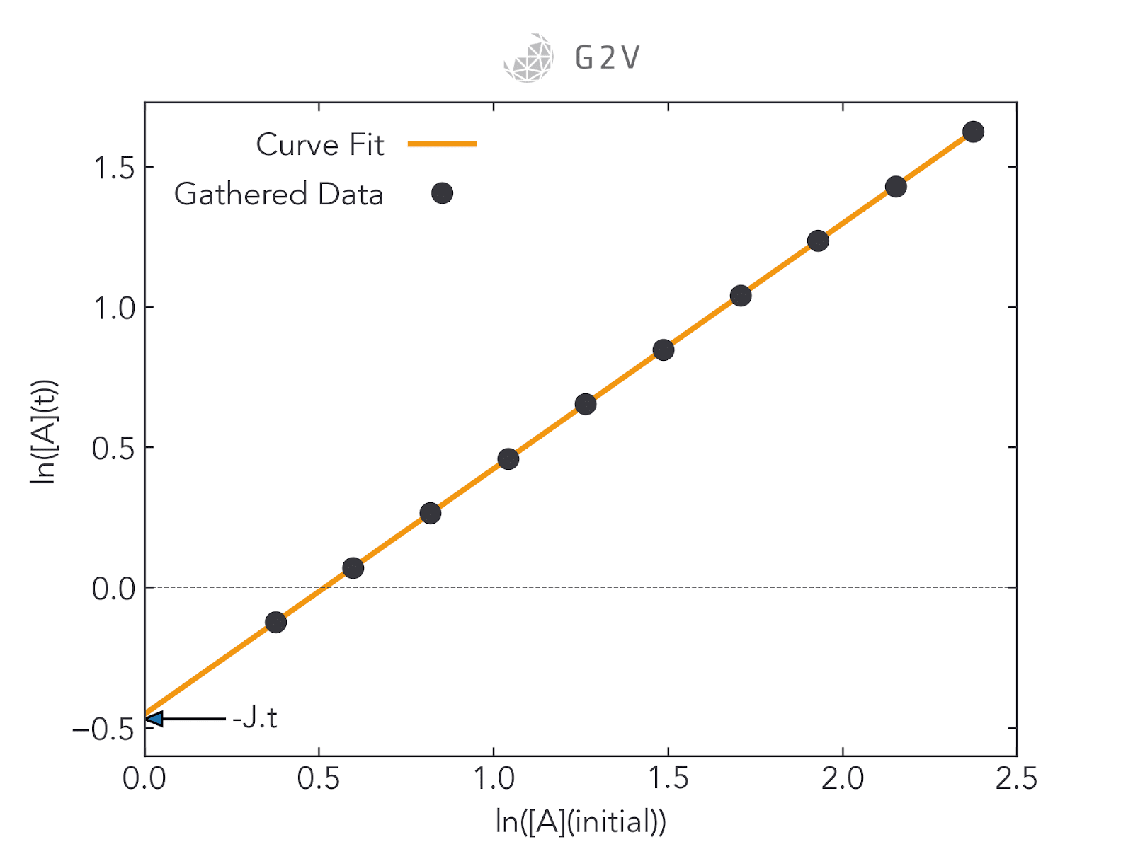
Scientists have subdivided UV radiation into different bands, primarily based on the levels of radiation damage on different materials and biology.
The figure below summarizes this division into UV-A, UV-B, UV-C, and V-UV (vacuum-UV, referring to UV radiation that’s generally only present in a vacuum).
Many of us are familiar with sunburns that can result primarily from UV-B radiation, with UV-A radiation also contributing to skin cancer formation.
As we rise in altitude, however, there’s less atmosphere to absorb much of this UV, so materials are exposed to more UV-A and UV-B. At an altitude of 10 km, for example, we receive four times more flux of 340 nm.
The ozone layer extends from about 15 km to 30 km, meaning that at those altitudes, we’re going to receive more and more unfiltered UV-C radiation.
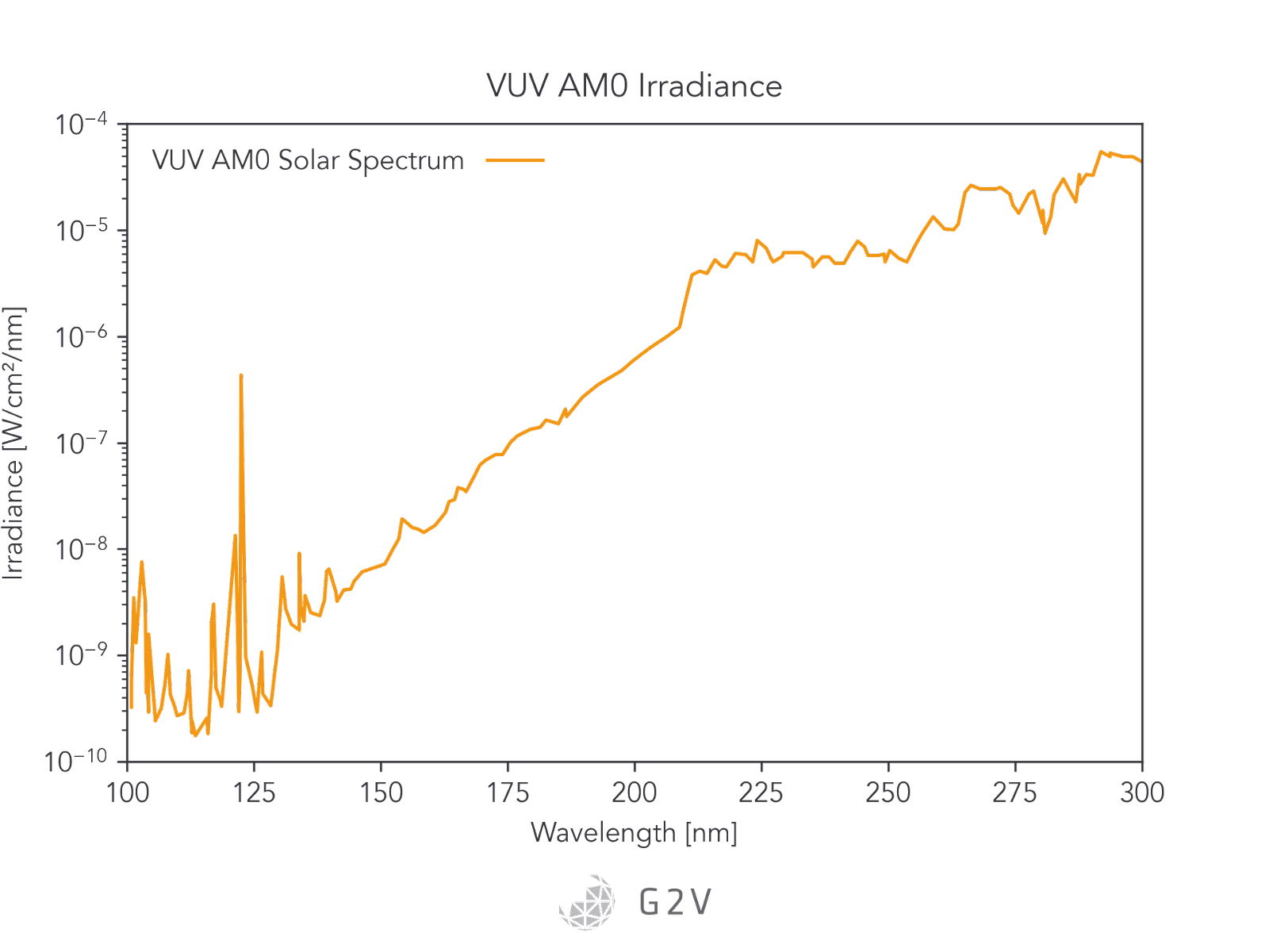
Finally, as we go outside of the Earth’s atmosphere, we are exposed to V-UV (vacuum-UV) radiation from 100 nm to 200 nm. Beyond the Earth’s atmosphere, solar radiation comprises 45% infrared, 48% visible light, and 7% UV.
Although the percentage and intensities of V-UV and UV-C radiation are lower than the rest of the spectrum, these photons have the highest energies, and often therefore have some of the highest capacities for damaging materials via photochemical evolution.
The UV spectrum in outer space is plotted below.
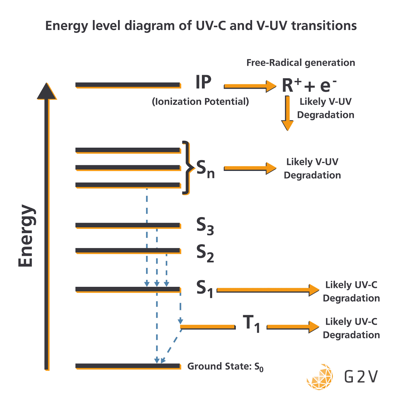
UV radiation can cause molecules to transition to excited electronic states. Some of these electronic states can react with surrounding materials and lead to degradation pathways. UV-C, having lower energy, generally results in the lowest-energy excited states, while V-UV produces higher-energy excited states, as shown in the energy diagram below.
The flux generally determines the population (or particle density) in each of the states. The exact details will vary depending on the material type(s), electron levels and bond strengths, but these are the general trends.
There’s also the possibility of complete ionization of the electron, leaving behind a highly-reactive ion. Chemical bonds can be completely cleaved by UV as well, which can produce a free radical (an atom or molecule with unpaired electrons) that can react with just about anything, with a typical example being the formation of atomic oxygen in Low-Earth Orbit.
In summary, the radiation environment is going to contain much more UV-C for aircraft journeying into the stratosphere, and both UV-C and V-UV for spacecraft venturing outside our planet.
In the sections below, we’ll discuss each of these UV radiation type’s ultimate impact on material performance.
The Impact of Unfiltered UV-C Light on Aircraft
UV-C light describes light with wavelengths from 200 nm to 280 nm.
Because this light is not present in regular atmospheric sunlight, its material degradation processes and pathways are not as widely understood, which is one of the reasons why it is so important for further research and testing.
We do, however, know how some materials respond to UV-C light.

Generally, metals are mostly unaffected by UV-C light.
Ceramics, with their higher bond energies, are also mostly unaffected.
Polymers (and carbon double-bonds in particular), have bond energies comparable to UV-C light, and so are susceptible to bond cleavage, also referred to as chain scission by photolysis.
Silicon dioxide (SiO2) or glass, exhibits ionic and covalent bond behaviour that makes it also susceptible to UV-C degradation. Impurities in glass, or atomic defects, can result in differential UV-C absorption that can create colour centers in glass, sometimes called solarization.
Outgasses produced during any UV-C degradation can be highly reactive, or toxic to aircraft passengers.
There are many everyday physical manifestations of UV-C degradation, including chalking/yellowing of PVC pipes, colour-fading on outdoor posters, and embrittlement of wire insulation.
UV is the primary cause of photo-oxidative degradation of coatings.
Unfortunately, many aircraft coatings and paint are made of organic coatings – in other words, polymers which are highly susceptible to UV-C photodegradation.
Polyurethane coatings, for example, have been extensively tested for aircraft. Aircraft coatings serve both protective and aesthetic functions, shielding against corrosion and other environmental effects in order to make the aircraft more safe and durable overall.
Aesthetically, coatings carry and project an airline’s brand around the world. Because of varying absorption coefficients, the coating surface temperature is often higher than air temperature, and this is especially true for darker colours.
Because of the strong absorption of UV-C radiation by organic materials, the surface layers of coatings are most prone to photodegradation.
Coating failure can ultimately lead to corrosion, cracking, and the need to replace portions or all of an aircraft.
UV-C is therefore a major concern for aircraft manufacturers. Spacecraft manufacturers have to not only contend with UV-C degradation pathways, but also the more extreme effects of higher-energy V-UV radiation, which we’ll discuss next.
Vacuum-UV (V-UV) Impact on Thermal Control Materials
Researchers have found that V-UV radiation is the most responsible for chemical evolution of organic matter, so understanding the physical processes it can induce is essential for outer space ventures.
The Sun’s irradiance in the V-UV region (100 nm to 200 nm) is dominated by the Lyman-alpha line at 121.6 nm, a spectral line of hydrogen. This spectral emission peak is the main driver of the physical interactions between UV radiation and materials. It’s responsible for between 15% and 85% of photoemission from spacecraft materials.
Perhaps because many spacecraft are enveloped by thermal control materials, these are the same materials that show the most significant degradation from V-UV exposure.
Degradation in thermal control materials manifests in polymers and thermal paints as surface erosion and an absorption increase (i.e. darkening).
The change in absorption is the biggest concern, because the original thermal balance / dissipation of the spacecraft was designed with a specific absorption spectrum in mind. Photodegradation of spacecraft materials ultimately results in a temperature increase of the spacecraft as these thermal control materials deteriorate.
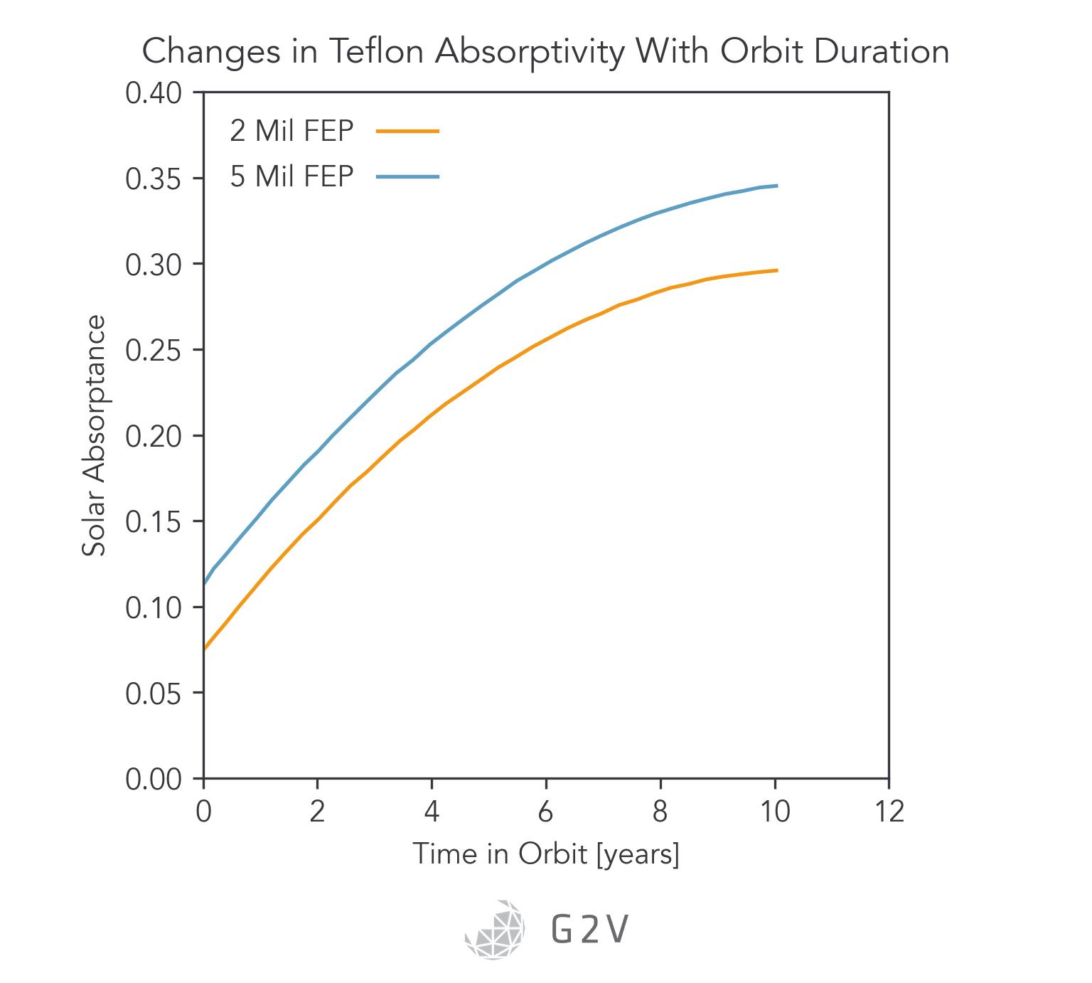
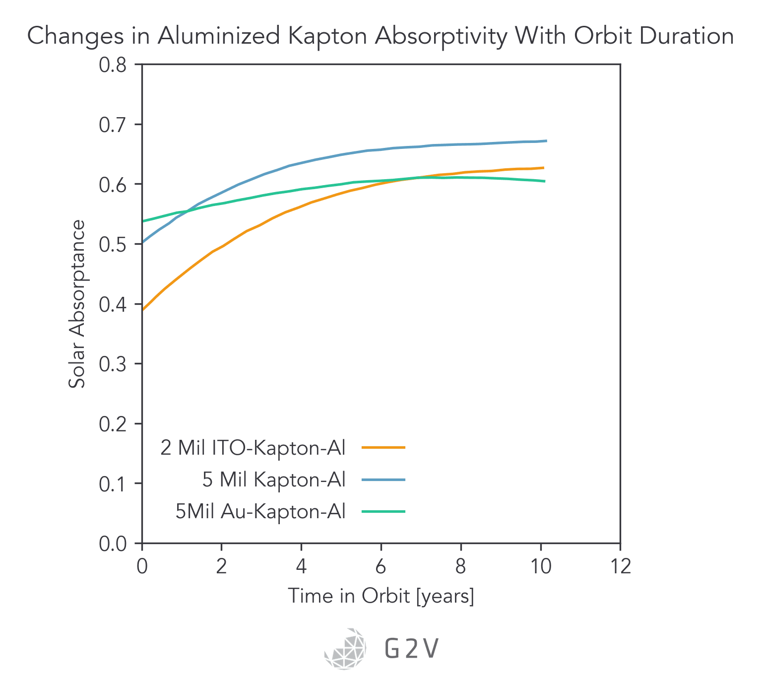
Specific examples of thermal control materials include aluminized Kapton and silverized Teflon, which showed heavy degradation when extracted from the Solar Maximum Mission satellite.
Because V-UV can also bond-cleave oxygen molecules to produce atomic oxygen, reactions with atomic oxygen are another degradation pathway in space (more specifically, in Low-Earth Orbit, LEO). Leading edges of satellites are weathered more severely than trailing edges. However, both leading and trailing edges experience UV radiation and significant erosion.
From the graphs below, we can conclude that major changes in solar absorption as a result of V-UV exposure can occur, and these may bring spacecraft outside of their expected thermal operating regimes. The ability to vet these materials to prevent a premature mission failure can’t be understated.
V-UV and UV-C generation of atomic oxygen results in external contaminants reacting with the outer layers of a spacecraft, a process known as photofixation (where a contaminant adheres to the surface as a result of photon-assisted reaction). Not only does such photofixation significantly degrade the thermal performance, but it also creates accretion centers promoting more contaminant growth.
For solar or optical materials, contaminant layers severely degrade their optical performance.
Outgassing of materials in vacuum is complicated by the high velocities typically involved in space applications. Test setups to try and accurately mimic the adsorption rates and emission rates encountered in orbital applications are challenging, to say the least.
Hopefully, we’ve provided you with an overview of some of the degradation and material concerns for the aerospace industry.
Next, we’ll discuss how researchers can quantify this degradation and thus begin to get a handle on how to mitigate unwanted photodegradation.
How Aerospace Researchers Quantify Photodegradation
We’ve already discussed some of the more common signs of a photodegraded material, such as yellowing and embrittlement.
It’s not always obvious how to quantify or measure the photodegradation of a material, however, since material researchers often want to know that the degradation occurred before these severe effects happen. It’s also possible for some degradation pathways not to exhibit easily-observed physical changes.
One way to quantify degradation is through loss of gloss, which is a precursor to some other degradation signs.
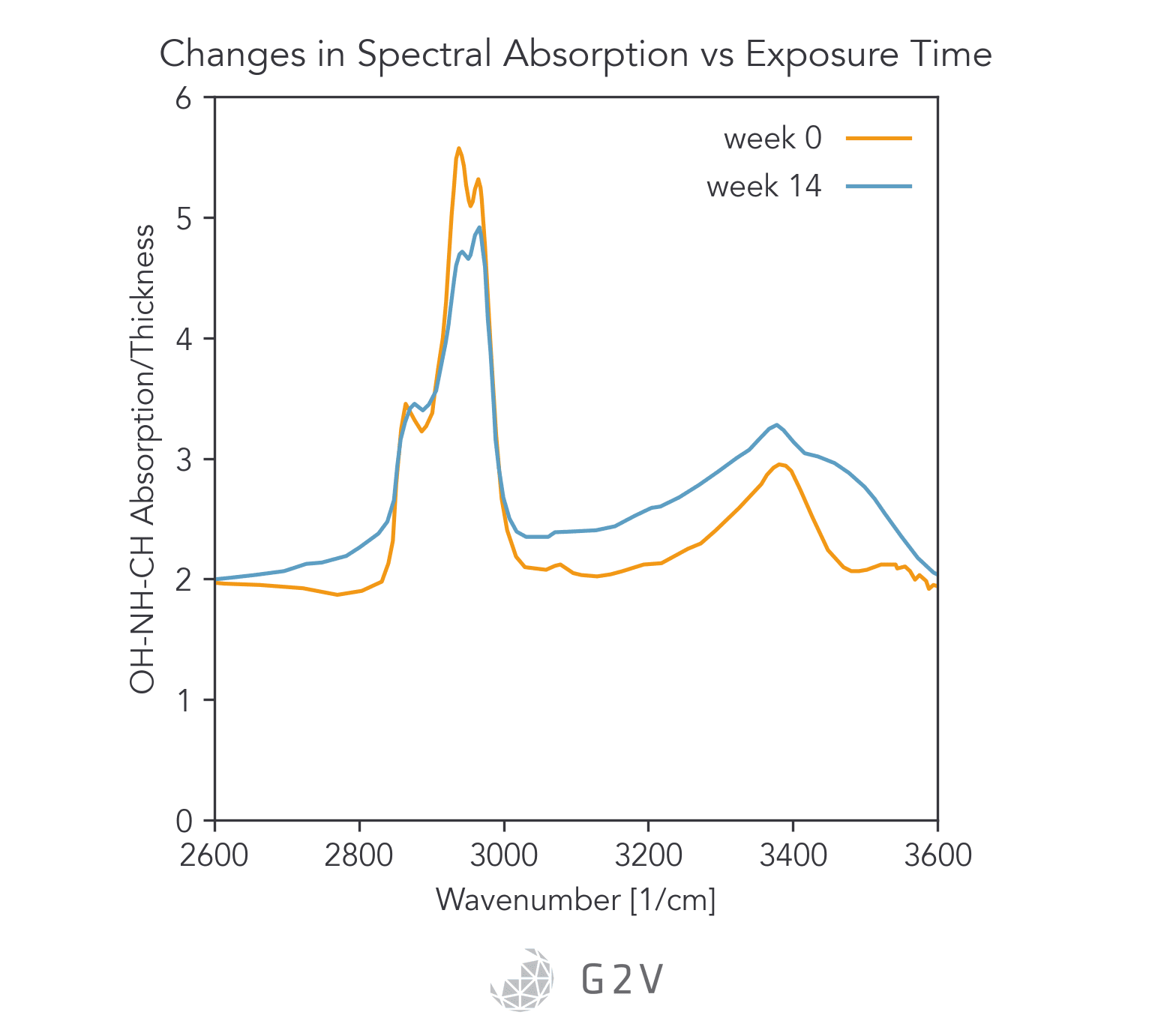
Another way to study degradation is by looking at spectral absorption in more detail with a spectrometer, such as in the Figure below.
Another way to quantify photodegradation is via material thickness, which can be measured by interferometry.
Bulk physical parameters (such as Young’s Modulus, tensile modulus, etc.) can also be used, and are more direct quantifications of key performance parameters. However, the measurement of some parameters may be more destructive than others, and so are less desirable for ongoing monitoring of a long-term test.
Researchers are therefore often interested in characteristics they can monitor in-situ, or without destroying part or all of the material sample. The first example we gave, gloss, is one good characteristic that can be measured non-destructively.
Once a researcher has a non-destructive characteristic they can use to quantify the extent of photodegradation, they’re often interested in executing lifetime tests. However, they don’t want to wait a full 25 years to know the degradation pathway; they’d like to accelerate such testing, which is what we’ll discuss next.
Relating Accelerated Photodegradation to Service Lifetime
While there are some standards for executing accelerated testing of materials (some of which have been done for over a hundred years), a helpful way to understand the approach is by looking at an example.
This example is a typical Service Life Prediction (SLP) method.
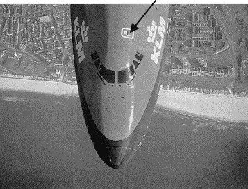
One of the ways aircraft coating degradation can be quantified is through loss of gloss, because it is a good precursor to cracking and delamination. A group of researchers applied different coatings to the escape hatches of B-747 aircraft for natural exposure tests.
Gloss measurements were taken in order to produce an accurate life distribution to describe the times-to-failure of the coating at the expected operating conditions. The ultimate purpose was to obtain the probability density function (pdf) of the times-to-failure, from which other reliability parameters can be derived, such as the mean time to failure (MTTF), mode life, and the percentage failing under warranty.
The researchers compared the real-life probability density function to results they obtained from accelerated exposure tests from a solar simulator and weather chambers.
A standard procedure is often to expose materials to condensation of water without UV radiation followed by a dry period with UV radiation.
The researchers’ challenge was then to be able to draw a link between the two data sets, which is known as the life-stress relationship. There are commonly used life-stress relationships in accelerated testing and SLP, listed below.
|
Name of Life-Stress Relationship |
Where and When it is used |
|
Arrhenius |
When temperature is an accelerating factor |
|
Inverse Power Law |
For non-thermal accelerated stresses |
|
Eyring |
For thermal or humidity stresses |
A list of common life-stress relationships that can link accelerated test data to service lifetimes. Taken from https://doi.org/10.1016/S0141-3910(03)00124-1.
In this study, the researchers used the Arrhenius life-stress relationship for temperature, and an inverse-power-law relationship for UV irradiance.
They added a third stress factor for aerosol presence, and were ultimately able to show good agreement between their experiment and their model.
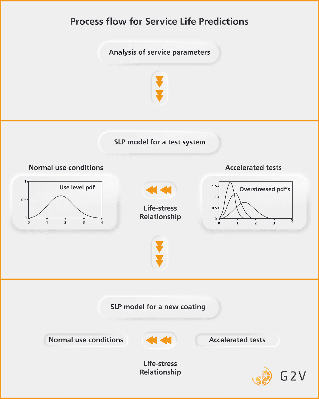
The overall process for Service Life Prediction can be understood through the diagram below.
The general flow is to analyze the key service parameters that can indicate failure, generate a model for a test system, gather the data to calibrate the normal and accelerated tests to one another through a life-stress relationship, then use that model for future material degradation predictions.
This study is an excellent example of how to interrogate and quantify degradation mechanisms in the aerospace industry.
It is quite common for accelerated lifetime testing of aircraft to be carried out under the sun’s irradiance at an altitude of 10 km.
Stress levels of UV radiation are usually between 0.4 W/(m2 nm) and 0.6 W/(m2 nm). Regular-use levels of UV radiation are around 0.2 W/(m2 nm).
Stress levels in accelerated testing have to be carefully chosen so that the material executes the same aging processes and does not pass through another degradation pathway that won’t occur under service conditions.
For more specific guidance on accelerated testing, here are the standards that can be used: ISO 11507 (Paints and Varnishes – Exposure of Coatings to Artificial Weathering – Exposure to Fluorescent UV and Water) and ASTM G151 (Standard practice for exposing nonmetallic materials in accelerated test devices that use laboratory light sources).
Solar Simulator Features that are Good for Aerospace Materials Testing
While solar simulators won’t necessarily provide all the requirements for aerospace material testing, they can still provide significant verification of material response to electromagnetic radiation.
Below are some of the solar simulator features you may want to seek out for this particular application.
Reproducing Orbital Particle Flow Conditions
As mentioned above, outgassed particles as a result of V-UV or UV-C radiation will often occur in-flight or in-orbit at high velocities. Therefore, having a solar simulator that can suitably accommodate such particulate flow (often in a vacuum chamber) may be advantageous.
This ties in more generally to a need for solar simulator integration with weathering chambers, which we’ll discuss below.
Testing Two or Three Different Environmental Parameters
Because aerospace material weathering occurs as a result of temperature, humidity, UV, and/or space weather, it is desirable to be able to test some or all of these effects simultaneously with one another.
While space weather is typically very difficult to reproduce on the ground, temperature, humidity and UV are more within reach.
Typically the testing of environmental parameters will be done in combinations of UV radiation along with temperature, or a combination of temperature, humidity and radiation.
Humidity is tested by cycles of dryness and wetness via spraying, condensing or flooding. As we mentioned above, aerosols and salt sprays can also be of value, and included as part of humidity testing.
Temperature is often controlled in a chamber. Radiation is often provided by a solar simulator or equivalent UV bulb.
Many solar simulators are available as part of a weathering chamber, or are suitable for integration into a weathering chamber.
It’s often ideal to keep the solar simulator’s lamps isolated from the harsh conditions of the humidity, which might mean illuminating through a window.
Choosing an appropriate window material that won’t absorb the key UV of interest is essential. Because so many materials absorb UV, however, if you need deep-UV exposure then it may be essential for your solar simulator light source to be mounted inside the chamber, in which case you’ll want to ensure that it can be suitably shielded from any salt-spraying or humidity effects.
Because of these logistical challenges, many material testers will opt for separate humidity and radiation tests.
It’s worth asking a solar simulator manufacturer whether they have experience with weathering chamber integration and can make any recommendations, since they may have already developed a good solution for your needs.
Spectrum Scheduling for Accurate Temporal Cycling
One group of researchers investigating material stresses from radiation exposure in Low-Earth Orbit found that the major discrepancy between laboratory and in-situ orbital exposure tests was due to the laboratory’s inability to reproduce the temporal variations in temperature and photon flux.
In this case, the discrepancy between simulated light and reality was so great that it was difficult to compare the two sets of results.
Specifically, the solar simulator wasn’t producing the 40 seconds out of each minute during the minute-long orbital period when the samples were in darkness. This resulted in a lower in-orbit concentration of photogenerated hydroxyl radicals (OH) as well as lower sample temperature, both of which led to a different relative humidity and altered rate of organic material degradation.
This situation, therefore, is something material researchers will want to avoid, and they can do so by using a solar simulator with a programmable and adjustable output spectrum.
Traditional bulb-based solar simulators such as xenon-arc or metal-halide typically achieve spectral match via glass filters, and therefore have a difficult time adjusting their output for cyclical exposure tests.
LED solar simulators, on the other hand, are well-suited for tuning individual LEDs in order to programmatically vary the illumination output for more accurately matching the anticipated spectrum variations in the atmosphere or in orbit.
The particular spectrum variations that the above-mentioned researchers found were related to the absorption bands of calcium ions around 400 nm. The researchers attributed the variation of these absorption features to the increase or decrease of solar activity.
Having a solar simulator that can adequately vary the flux in such specific spectral regions would greatly improve the fidelity between laboratory and real-world results.
Simulating Spectra at Altitudes of 10 km
Most accelerated life testing of aircraft and aircraft materials occurs at altitudes of 10 km, so the ability to produce the spectrum here is a common solar simulator requirement.
The most common UV fluorescent bulbs are the 340-UVA and 313-UVB. Their spectra are depicted in the graph below, along with the sun’s spectra at 1 km and 10 km.
Two of the most common solar simulator technologies, xenon and LED, are also plotted against the solar spectrum to illustrate the assortment of available options.
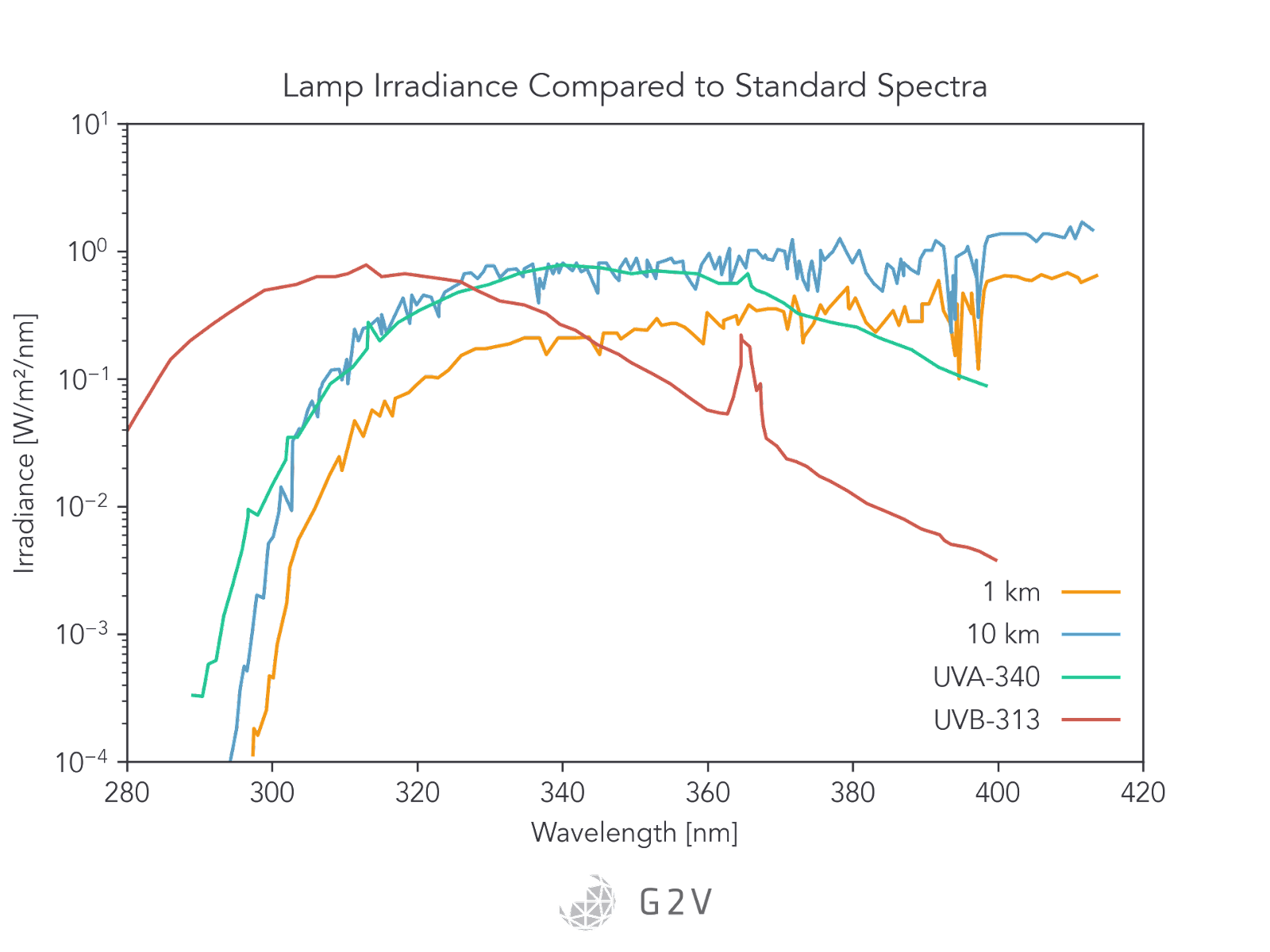
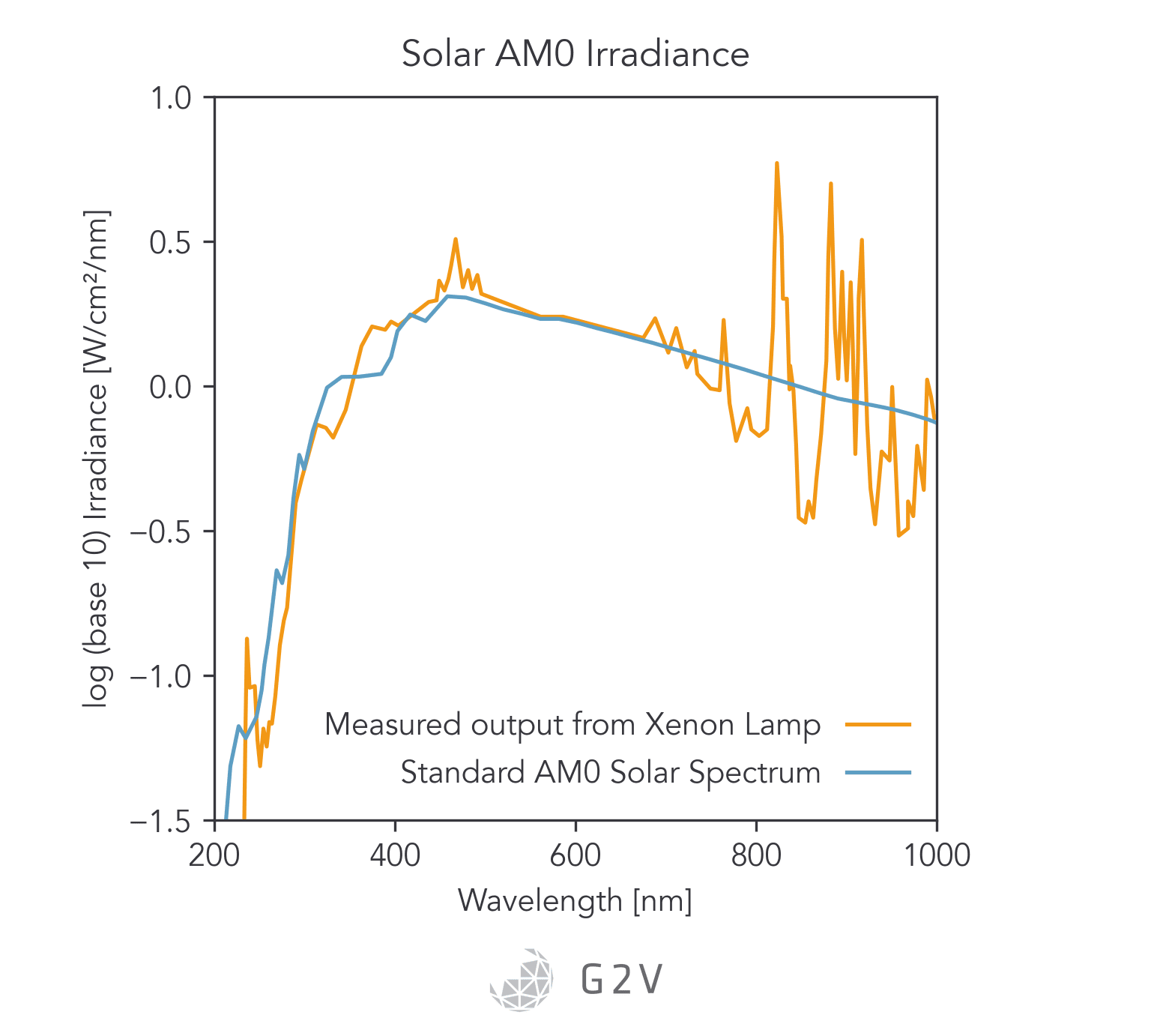
As may be evident from the Figure, the 340-UVA fluorescent bulb is a better match to sunlight between 300 nm and 360 nm. It’s worth noting that this bulb still doesn’t have UV-C light, and so depending on the application may not completely test all the possible photodegradation pathways.
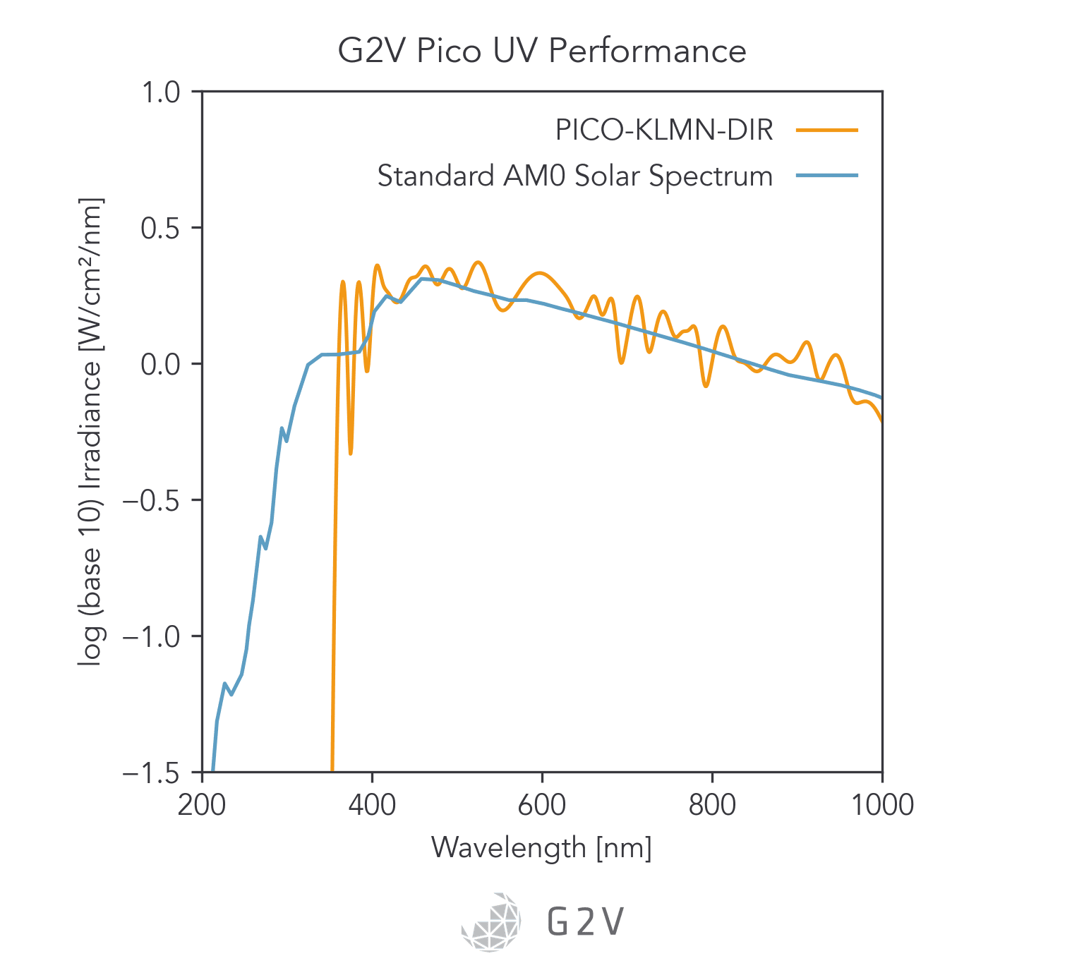
As far as LED-based solar simulators, they are much more amenable to tuning because they are constructed from individual light sources.
However, commercially available LEDs in the UV range can be cost-prohibitive and low-flux, which means that the lower wavelength limit may be restricted to approximately 350 nm, which will definitely exclude many photodegradation pathways.
LED technology is an active area of research and development, and so it’s worth monitoring the current state for significant advances that can push emissions deeper into the UV and make UV-C testing with LEDs more viable.
Such a solution would have great advantages over the traditional short-lifetime, high-temperature bulbs.
Simulating UV-C Light for High Altitudes and Space
Currently, xenon arc lamps are most suitable for producing UV-C light, since they can emit wavelengths as low as 147 nm. It’s possible that other gas discharge lamps may be able to produce similar results to xenon (such as metal-halide), but for UV emission in particular xenon is the most common.
The other common UV-C light source is LEDs, which are usually more efficient and compact. LEDs produce different emission wavelengths by changing the source material’s semiconductor band gap.
Common blue LEDs, for example, are made from indium gallium nitride (InGaN). To achieve a wider band gap (i.e. a higher energy emission deeper into the UV), aluminum gallium nitride (AlGaN) is used as a ternary compound.
The material science around UV-C LED compounds is still quite nascent, and as a result there are several limitations which have yet to be overcome. The commercial lifetime of UV-C LEDs is quoted as several thousand hours, which is a far cry from the 50,000 to 100,000 hours some manufacturers claim for other-wavelength LEDs.
Currently UV-C LEDs exhibit unique degradation mechanisms, such as the generation of defects in the active area. UV-C LED degradation is also more prominent at high temperatures and low currents. Recommendations for UV-C LEDs are often to expect steady decline in their output power, which puts them in the same behavioural realm as xenon arc lamps.
Therefore, while UV-C LEDs are available for wavelengths as low as 250 nm (and researchers have gone even further to 210 nm), their lifetime and degradation make them less than ideal for solar simulation.
However, interest in UV-C LEDs has increased tremendously as a result of the COVID-19 pandemic and a strong need for UV-C antiviral technology. With such a strong market drive, it’s likely we can anticipate some significant developments in this field, which would make UV-C LEDs more suitable for solar simulation.
Simulating V-UV light for Aerospace Material Testing
When it comes to V-UV light testing, the primary challenge is being able to find a source to emit in this region of the electromagnetic spectrum.
The challenge of finding a suitable ground source has led to an ongoing need to validate ground tests by sending comparative samples into space.
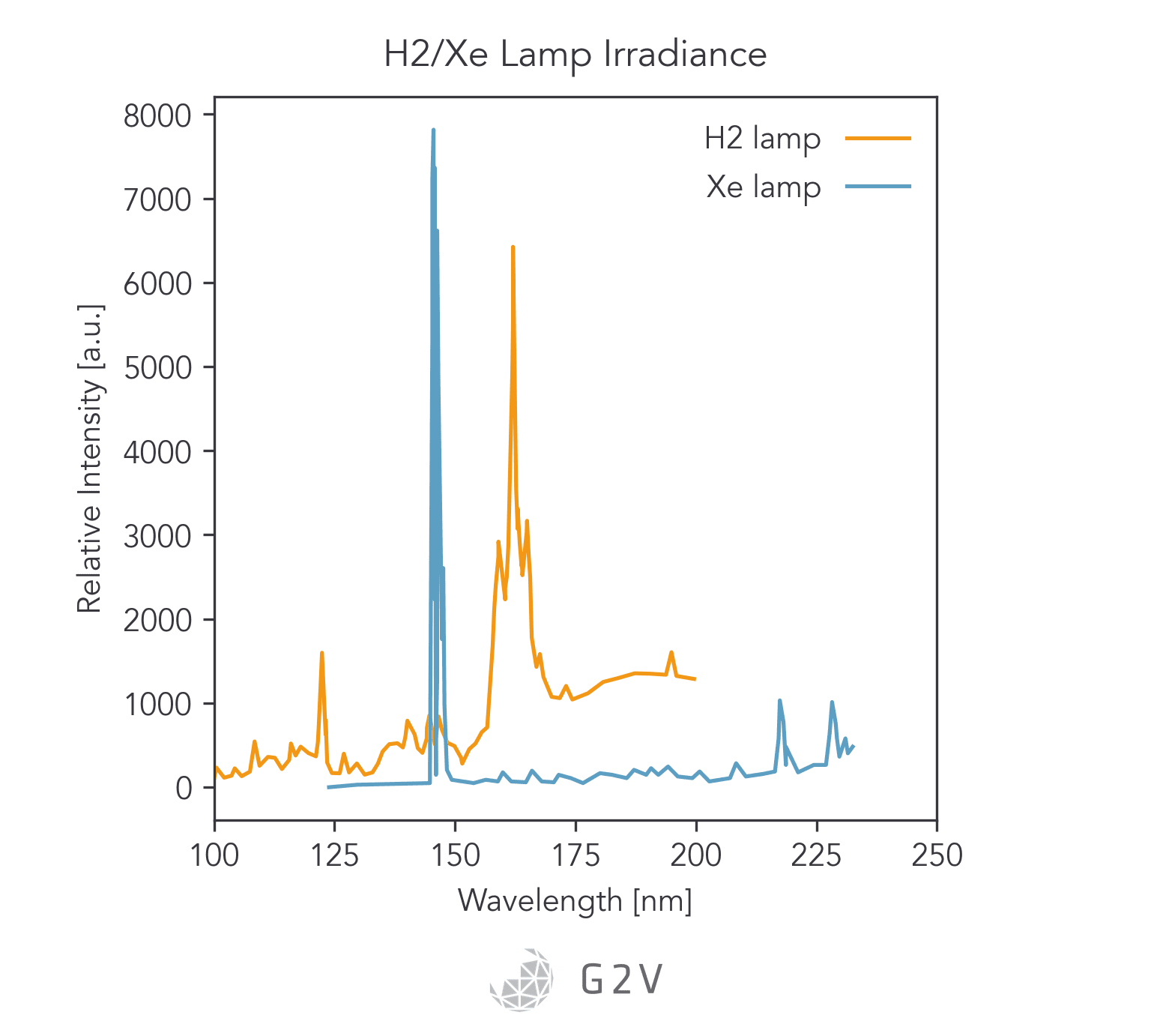
One common strategy to try and produce V-UV light on the ground is to use a xenon-arc lamp with a Magnesium Fluoride (MgF2) window to produce light with wavelengths as low as 147 nm.
Another strategy is to Irradiate a gas with microwaves to produce a plasma that then emits specific lines of interest.
A typical arrangement of the gas flow, microwave emitter and sample is shown below.
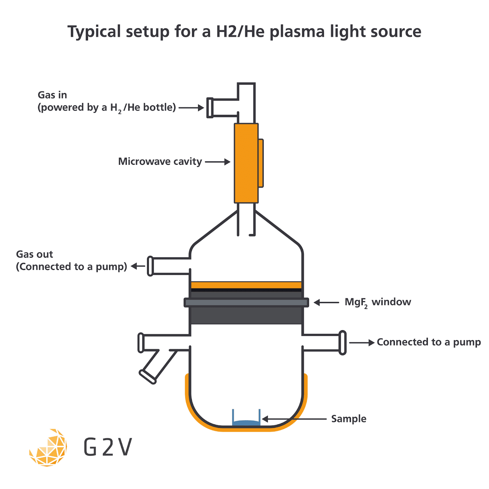
A microwave-irradiated mixture of methane (CH4) and helium (He) will emit around 193 nm, for example, while a 4 mbar mixture of 2% hydrogen (H2) in helium (He) will emit around 121 nm.
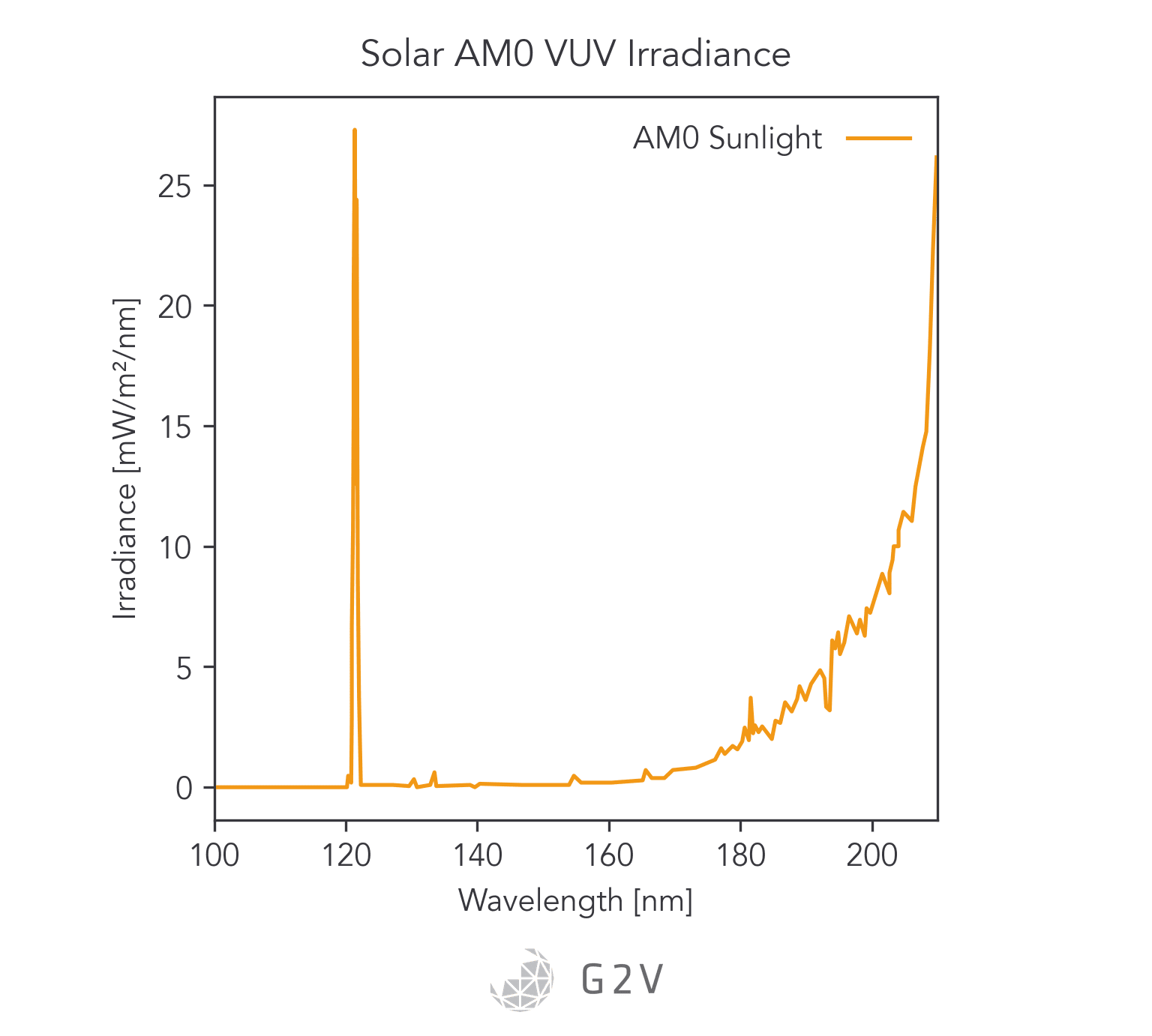
In the 100 nm to 150 nm region of the solar spectrum, the majority of the flux is from the Lyman-alpha emission of atomic hydrogen at 121 nm.
Therefore, for V-UV light simulation, spectral match of this peak is of primary interest, because this peak contributes significantly to material degradation.
A focus on the Lyman-alpha line leaves us with the plasma-emission strategy. The challenge with this strategy is that the monochromaticity and spectral distribution are highly sensitive to gas pressure, mixing ratio, microwave power, color centers in the MgF2 windows, and temperature fluctuations. Electrode position within the cavity also plays a role.
Ultimately the rate of material photodestruction is hard to quantify in this experimental setup, because calibrating the emission source requires vacuum-based instrumentation that is costly and often impractical. Predicting reaction rates requires knowing the molecular absorption coefficients. A lack of a stable, calibrated source makes determination of these absorption coefficients very difficult.
A synchrotron source is one option for V-UV investigations, but this is typically limited to very small samples, or small exposures.
NASA’s Ames Research Center developed the O/OREOS nanosatellite, O/OREOS (Organism/Organic Exposure to Orbital Stresses) that launched in 2011, to expose samples to V-UV radiation and investigate these particular material decay mechanisms. This is an example of the type of in-situ testing that may become increasingly viable as cubesat launches decrease in cost.
Unfortunately, however, there aren’t currently good commercial solutions for full V-UV testing on the ground. As we mentioned above, traditional bulb emissions from xenon-arc lamps only reach as low as 147 nm.
LED technology also struggles to produce V-UV light, with a commercial lower wavelength limit of about 250 nm. While LED technology is likely to improve, high-energy UV LEDs will likely remain on the leading edge of materials research and will therefore be quite costly and/or unreliable.
We previously mentioned the Marshall Space Flight Center’s Solar and Ultraviolet Radiation test facility, which provides holistic space weather testing including V-UV. This is a viable path for V-UV ground testing.
However, having the funds and getting access to this facility can be challenging.
Therefore, for V-UV testing, commercial solar simulators are currently not a good solution, aside from perhaps being capable of easily integrating with a H2/He plasma source in order to supplement them to result in full-spectrum illumination.
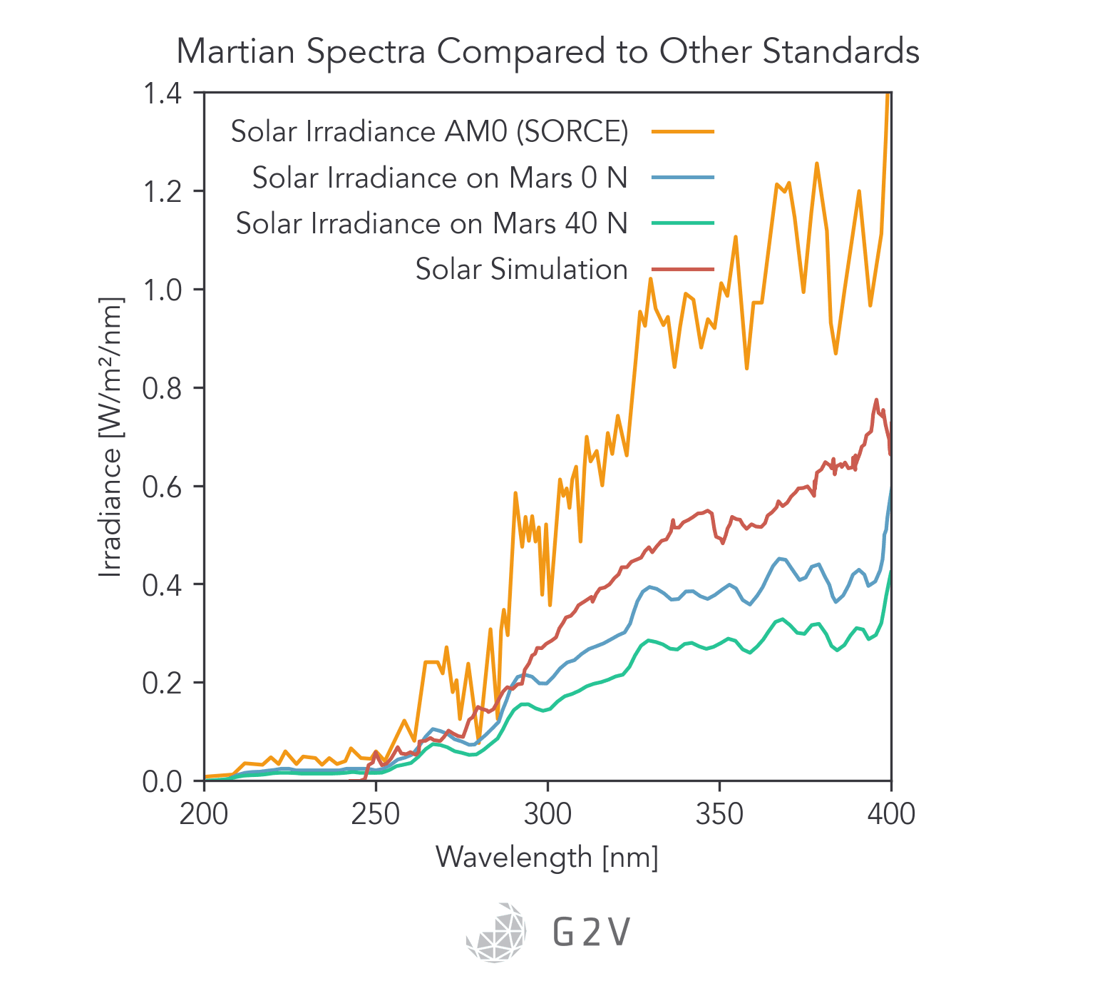
There are some outer space environments that can be appropriately reproduced by a solar simulator, such as the Martian atmosphere, where atmospheric absorption removes the Lyman-alpha line and results in a spectrum that starts at approximately 190 nm and has a total irradiance of approximately 44 W/m2.
For extrasolar spectra where the Lyman-alpha line is not present for whatever reason, solar simulators can be an excellent test tool.
Higher Intensities for Accelerated Testing
As we discussed above, manufacturers can’t afford to wait for the results of a twenty-five year lifetime test.
Accelerated testing is essential, and this means illuminating with a higher irradiance than a material would normally see.
Solar simulators are available that produce multiple suns’ worth of intensity in order to facilitate this type of accelerated photodegradation. Traditionally, high-intensity solar simulators were the realm of bulb-based technologies such as xenon and metal-halide, but with the advent of higher-efficiency, high-power LEDs, multi-sun LED solar simulators are now viable.
Skin, Eye and Ozone Safety Concerns When UV Testing
UV radiation is quite dangerous, as you might have gleaned from all of the degradation pathways mentioned in this article.
It is therefore quite important that any solar simulator come with suitable safety measures incorporated into the design, as well as general guidance for safely operating the equipment. Ozone can be produced by UV-C radiation, so a proper method for managing this hazard is necessary.
This may,for example, require purchasing and integrating a commercially-available ozone scrubber.
A good solar simulator manufacturer will be able to provide safety guidance for safely using the output light as well as dealing with the photochemically generated ozone and other by-products.
For further information on the hazards of solar simulators in this wavelength regime, see this excellent resource.
Aerospace Materials Testing Summary; TLDR
Aerospace material testing is extremely challenging because, as we’ve seen, it involves so many extreme environmental factors.
However, such testing is essential because of the higher risks involved in any aerospace application.
Thankfully, there are many tools available to help researchers successfully derisk design and materials in advance of flight, and ultimately achieve mission success.
- Probing material degradation pathways on the ground, before flight or launch, can help avoid costly mission failures
- Photodegradation is often long-term and manufacturers need to execute accelerated testing for viable material development roadmaps
- Ground testing allows for gathering reaction data on more than just the start and end points, thereby allowing for more accurate reaction rate and cross-section determination
- Space weather has a major effect on material degradation, but is very difficult to reproduce on the ground
- Aerosols, humidity, and temperature all influence material degradation, so a solar simulator that can be combined with this other testing is advantageous
- UV-C and V-UV light are the major drivers of photodegradation for aerospace materials, despite only representing a small portion of the solar spectrum.
- UV light can ionize materials, create free radicals, as well as cause polymer chain scission and colour center creation
- V-UV’s capability to erode surfaces and alter absorption profiles is a major concern for spacecraft
- UV-C light is currently best simulated by xenon-arc lamps, but keep an eye out for advancing UV-C LED technology
- V-UV light is very hard to reliably produce in ground testing; the best we have is unstable and hard-to-calibrate plasma emission
- High-intensity (multi-sun) solar simulators are ideal for accelerated material testing, but need to prioritize safety because of high-energy UV photons and the capacity for ozone creation
References
Brunner, S., Richner, P., Müller, U., & Guseva, O. (2005). Accelerated weathering device for service life prediction for Organic Coatings. Polymer Testing, 24(1), 25–31. https://doi.org/10.1016/j.polymertesting.2004.08.001
Burleigh, T. D., Ruhe, C., & Forsyth, J. (2003). Photo-corrosion of different metals during long-term exposure to ultraviolet light. Corrosion, 59(9), 774–779. https://doi.org/10.5006/1.3277606
Cook, A. M., Mattioda, A. L., Quinn, R. C., Ricco, A. J., Ehrenfreund, P., Bramall, N. E., Minelli, G., Quigley, E., Walker, R., & Walker, R. (2014). Sevo on the ground: Design of a laboratory solar simulation in support of the O/oreos mission. The Astrophysical Journal Supplement Series, 210(2), 15. https://doi.org/10.1088/0067-0049/210/2/15
Cook, A. M., Mattioda, A. L., Ricco, A. J., Quinn, R. C., Elsaesser, A., Ehrenfreund, P., Ricca, A., Jones, N. C., & Hoffmann, S. V. (2014). The organism/organic exposure to orbital stresses (O/oreos) satellite: Radiation exposure in low-earth orbit and supporting laboratory studies of Iron Tetraphenylporphyrin Chloride. Astrobiology, 14(2), 87–101. https://doi.org/10.1089/ast.2013.0998
Cottin, H., Coll, P., Coscia, D., Fray, N., Guan, Y. Y., Macari, F., Raulin, F., Rivron, C., Stalport, F., Szopa, C., Chaput, D., Viso, M., Bertrand, M., Chabin, A., Thirkell, L., Westall, F., & Brack, A. (2008). Heterogeneous solid/gas chemistry of organic compounds related to comets, meteorites, Titan, and mars: Laboratory and in Lower Earth orbit experiments. Advances in Space Research, 42(12), 2019–2035. https://doi.org/10.1016/j.asr.2007.09.017
Cottin, H., Kotler, J. M., Billi, D., Cockell, C., Demets, R., Ehrenfreund, P., Elsaesser, A., d’Hendecourt, L., van Loon, J. J., Martins, Z., Onofri, S., Quinn, R. C., Rabbow, E., Rettberg, P., Ricco, A. J., Slenzka, K., de la Torre, R., de Vera, J.-P., Westall, F., … Klamm, B. A. (2017). Space as a tool for astrobiology: Review and recommendations for experimentations in Earth orbit and beyond. Space Science Reviews, 209(1-4), 83–181. https://doi.org/10.1007/s11214-017-0365-5
Dibowski, G., & Esser, K. (2017). Hazards caused by UV rays of xenon light based high performance solar simulators. Safety and Health at Work, 8(3), 237–245. https://doi.org/10.1016/j.shaw.2016.12.002
Elsaesser, A., Quinn, R. C., Ehrenfreund, P., Mattioda, A. L., Ricco, A. J., Alonzo, J., Breitenbach, A., Chan, Y. K., Fresneau, A., Salama, F., & Santos, O. (2014). Organics exposure in orbit (OREOcube): A next-generation space exposure platform. Langmuir, 30(44), 13217–13227. https://doi.org/10.1021/la501203g
Environmental Protection Agency. (2021, October 7). Basic Ozone Layer Science. EPA. Retrieved September 10, 2022, from https://www.epa.gov/ozone-layer-protection/basic-ozone-layer-science
Gronstal, A. L. (2012, March 23). O/oreos nanosatellite success in orbit. Phys.org. Retrieved September 10, 2022, from https://phys.org/news/2012-03-ooreos-nanosatellite-success-orbit.html
Guan, Y. Y., Fray, N., Coll, P., Macari, F., Chaput, D., Raulin, F., & Cottin, H. (2010). Uvolution: Compared photochemistry of prebiotic organic compounds in low Earth orbit and in the Laboratory. Planetary and Space Science, 58(10), 1327–1346. https://doi.org/10.1016/j.pss.2010.05.017
Guseva, O., Brunner, S., & Richner, P. (2002, September). Analysis of the environmental parameters for aircraft coatings. In Macromolecular Symposia (Vol. 187, No. 1, pp. 883-894). Weinheim: WILEY‐VCH Verlag. https://doi.org/10.1002/1521-3900(200209)187:1%3C883::AID-MASY883%3E3.0.CO;2-M
Guseva, O., Brunner, S., & Richner, P. (2003). Service life prediction for aircraft coatings. Polymer Degradation and Stability, 82(1), 1–13. https://doi.org/10.1016/s0141-3910(03)00124-1
High-Power UV LEDs with Ball Lens. Thorlabs. (n.d.). Retrieved September 10, 2022, from https://www.thorlabs.com/newgrouppage9.cfm?objectgroup_id=8606
ISO 11507:2007. ISO. (2013, November 6). Retrieved September 10, 2022, from https://www.iso.org/standard/37489.html
ISO 9227:2017. ISO. (2020, September 14). Retrieved September 10, 2022, from https://www.iso.org/standard/63543.html
Johnson, R. H., Montierth, L. D., Dennison, J. R., Dyer, J. S., & Lindstrom, E. R. (2013). Small-scale simulation chamber for Space Environment Survivability testing. IEEE Transactions on Plasma Science, 41(12), 3453–3458. https://doi.org/10.1109/tps.2013.2281399
Martínez-Manuel, L., Peña-Cruz, M. I., Villa-Medina, M., Ojeda-Bernal, C., Prado-Zermeño, M., Prado-Zermeño, I., Pineda-Arellano, C. A., Carrillo, J. G., Salgado-Tránsito, I., & Martell-Chavez, F. (2018). A 17.5 kwel high flux solar simulator with controllable flux-spot capabilities: Design and validation study. Solar Energy, 170, 807–819. https://doi.org/10.1016/j.solener.2018.05.088
National Aeronautics and Space Administration. (n.d.). Solar and ultraviolet radiation testing – NASA. NASA. Retrieved September 10, 2022, from https://www.nasa.gov/sites/default/files/atoms/files/g-33798_surt.pdf
Rockett, C. (2022, July 11). UV degradation effects in materials – an elementary overview ” Uv solutions. UV Solutions. Retrieved September 10, 2022, from https://uvsolutionsmag.com/articles/2019/uv-degradation-effects-in-materials-an-elementary-overview/
Sgambati, A., Deiml, M., Stettner, A., Kahrs, J., Brozek, P., Kapoun, P., Latini, V., Mariani, M., Rabbow, E., Manieri, P., Demets, R., & Elsaesser, A. (2020). SPECTROModule: A modular in-situ spectroscopy platform for Exobiology and Space Sciences. Acta Astronautica, 166, 377–390. https://doi.org/10.1016/j.actaastro.2019.10.010
Skaja, A., Fernando, D., & Croll, S. (2006). Mechanical property changes and degradation during accelerated weathering of polyester-urethane coatings. Journal of Coatings Technology and Research, 3(1), 41–51. https://doi.org/10.1007/s11998-006-0004-7
Standard practice for exposing nonmetallic materials in accelerated test devices that use laboratory light sources. ASTM International – Standards Worldwide. (2019, February 13). Retrieved September 10, 2022, from https://www.astm.org/g0151-19.html
Standard practice for operating salt spray (fog) apparatus. ASTM International – Standards Worldwide. (2017, August 16). Retrieved September 10, 2022, from https://www.astm.org/b0117-03.html
Stiegman, A. E., & Liang, R. H. (1993). Ultraviolet and vacuum-ultraviolet radiation effects on spacecraft thermal control materials. The Behavior of Systems in the Space Environment, 259–266. https://doi.org/10.1007/978-94-011-2048-7_11
Trivellin, N., Fiorimonte, D., Piva, F., Buffolo, M., De Santi, C., Meneghesso, G., Zanoni, E., & Meneghini, M. (2022). Reliability of commercial UVC leds: 2022 state-of-the-art. Electronics, 11(5), 728. https://doi.org/10.3390/electronics11050728
U.S. Geological Survey . (n.d.). The Cataclysmic 1991 Eruption of Mount Pinatubo, Philippines. The cataclysmic 1991 eruption of Mount Pinatubo, Philippines, fact sheet 113-97. Retrieved September 10, 2022, from https://pubs.usgs.gov/fs/1997/fs113-97/
Vanhove, E., Roussel, J.-F., Inguimbert, V., & Chardon, J.-P. (2016). UV photofixation of molecular contamination: Simulation of in-flight data. SPIE Proceedings. https://doi.org/10.1117/12.2238935
Wang, D., Jiang, S. H. A. N. P. I. N. G., Xiang, Y. A. N. H. O. N. G., Yang, L. I. N. H. U. A., & Wang, S. H. A. O. P. U. (2019). Design of medium solar simulator integrator. AOPC 2019: Space Optics, Telescopes, and Instrumentation. https://doi.org/10.1117/12.2542789
What is the difference between UVA and UVB rays? University of Iowa Hospitals & Clinics. (2016, July 2). Retrieved September 10, 2022, from https://uihc.org/health-topics/what-difference-between-uva-and-uvb-rays
Zhao, S., Connie, A. T., Dastjerdi, M. H., Kong, X. H., Wang, Q., Djavid, M., Sadaf, S., Liu, X. D., Shih, I., Guo, H., & Mi, Z. (2015). Aluminum nitride nanowire light emitting diodes: Breaking the fundamental bottleneck of deep ultraviolet light sources. Scientific Reports, 5(1). https://doi.org/10.1038/srep08332