Chapter 2
How Are Perovskite Solar Cells Made?
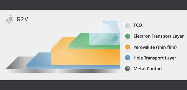
To create a perovskite you need to form the final structure from its component precursors. When the general ABX3 perovskite structure is the desired outcome, researchers and fabricators mix AX and BX2 precursors on a surface via one of the following methods for perovskite crystallization to occur.
These methods range from various solution processing, vapour phase or electrodeposition methods, illustrated in the figure below.
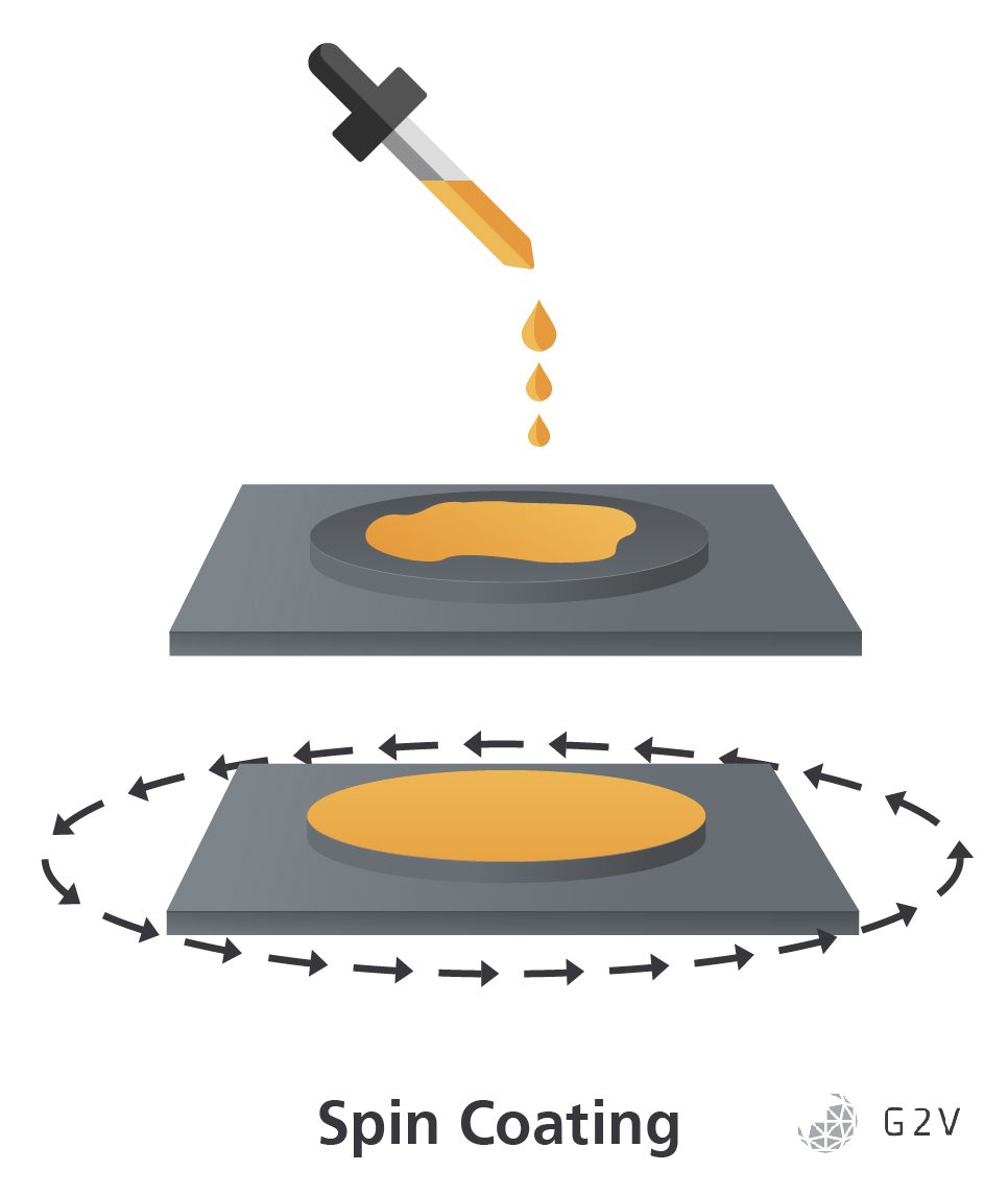
Spin-Coating: Benefits And Drawbacks For PSCs
Spin-coating is currently a standard method of perovskite fabrication for researchers. It is a rapid and low-cost fabrication method, allowing rapid iteration and production of small samples in labs.
By rapidly spinning a substrate that has a pool of mixed precursor inks (solutions made of the perovskite precursors AX and BX2 dissolved in volatile solvents) poured on it, it is possible to create a layer of a defined thickness by altering the speed of rotation relative to the viscosity and surface tension of the precursor ink. After spinning, the coated substrate is then heated to finalize the fabrication of the perovskite layer by crystallizing the precursors and driving off the remaining solvent after the crystallization. However, since the quality of the final crystal is governed by the concentration of precursors within the solvent which determines the rate of transport of the perovskite precursors from the liquid phase to the solid phase, if you heat everything too quickly you will drive off too much solvent, reducing the mobility of the precursors, ending up with poor quality crystals.
Problems with spin-coating arise when trying to scale up from small samples. Since the thickness of the final coating is determined by balancing the centripetal force of the rotation against the viscosity and surface tension of the perovskite precursor ink, increasing the size of the substrate being spun causes the force applied to the substrate to increase the farther the ink is from the center. This position-varying force on the substrate can lead to a coating that has a non-uniform thickness, because areas of low force will leave a thicker coating on the substrate, and areas of high force will leave a thinner coating or even break the coating up if the centripetal forces exceed the surface tension of the ink.
The other problem is that spin-coating tends to be a very messy process. By spinning the substrate to remove any excess material aside from a desired thin layer, by necessity, you end up wasting a large portion of your precursor ink, potentially up to 50 times more than other less vigorous processes (which we’ll discuss below).
Roll-To-Roll Fabrication: The Future Of Perovskite Manufacturing?
A scalable alternative to spin-coating for perovskite solar cell manufacturing is roll-to-roll processing which, while still operating in a liquid phase (thus falling under the umbrella of solution processing), has garnered noticeable interest in recent years.
Roll-to-roll processing is a catch-all term for processes that operate continuously via transport on one or more belted surfaces. This type of processing is desired so that the final product is a continuous sheet rather than a line of individual objects, and combines extremely well with the liquid phase solution processing methods used with perovskite solar cells due to the simplicity of transporting and applying liquid phase precursors to any substrate.
“Doctor” Blade deposition is the simplest method of applying thin films to a substrate. You position a blade, or another similar barrier, at a specific desired distance above the substrate surface and apply a pool of the desired material precursor in front of the blade such that the motion of the roll surface pulls the pool into the blade which then scrapes away all but the desired film thickness.
Compared to spin-coating, this is a mechanically simple process but it offers new considerations for stable and homogeneous crystal production. Lacking the same strong forces being applied to the precursor ink of the perovskite solar cells that spin-coating has, inks that are coated via blade deposition tend to retain higher solvent fractions at the heating stage. This is irrespective of the height of the blade above the moving substrate or the speed of the substrate as the blade is only meant to allow only a specific amount of material through to give the desired thickness of the film. This entails different crystallization rates and makes it more difficult to retain control over the formation of grain boundaries (the disordered interfaces within the material between two misaligned zones of single crystal material) and other assorted defects (discussed in more detail later).
Slot die coating is a variation of blade deposition where the precursor ink is applied directly to the substrate by pumping it through channels in a squared-off die nozzle placed directly perpendicular to the substrate. Coating thickness is determined not only by the spacing between the die and the substrate but also by the viscosity of the ink and by the speed of the substrate pulling the ink. This process has the advantage of being more temperature controllable as the die can be heated or cooled to allow for close-to-optimal pumping of the precursor ink, having a more controllable flow rate, and limiting the exposure of the perovskite precursor ink to the atmosphere and any oxygen prior to deposition.
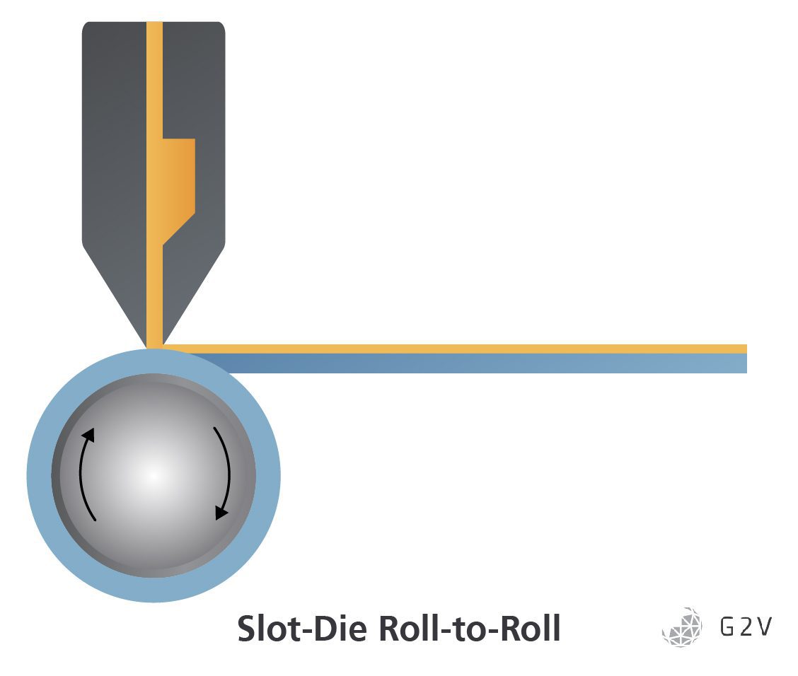
Because of the high degree of temperature control and lower chance of contamination prior to application in slot die coating, PSCs fabricated with this method have succeeded in joining spin-coated cells in achieving greater than 20% efficiency. However, slot die coating shares the downsides of blade deposition compared to spin-coating in that it retains a much larger fraction of solvent in the ink post-deposition due to the lack of high forces to preferentially remove any excess low-viscosity solvent, resulting in a more complicated and defect-prone crystallization process.
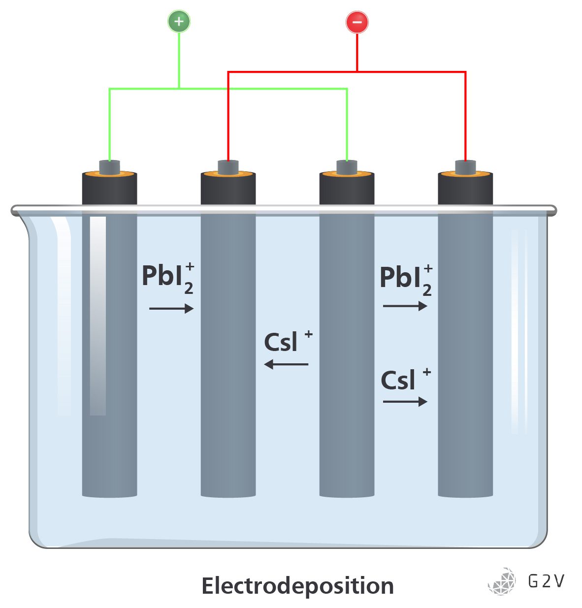
Electrodeposition: New Contender That Could Change The Game For Perovskite Manufacturing
More recently, an effort to provide the benefits of the low cost and rapid rate of solution processing while maintaining a more controllable surface structure has emerged through the use of electrodeposition methods.
Electrodeposition is a very mature manufacturing technology primarily used in the creation of high-purity metals. This deposition method first places electrodes into an electrolyte solution made up of the ionic components desired to be turned into a solid form. Applying an electrical bias across the electrodes forces oxidation-reduction reactions that convert the ions into solids that coat the electrodes. The rate of deposition and quality of the deposited crystals are determined by the voltage and current of the system. The application of materials onto the electrode is sometimes called plating.
While an electrodeposition system can significantly outperform a vapour deposition system in terms of throughput, it does have its limitations to overcome to achieve high-efficiency perovskites.
Firstly, it is challenging to prevent heterogeneous nucleation upon the substrate electrode, meaning that the perovskite structures are likely to be multi-crystalline and suffer from the known reductions in efficiency that a high density of charge carrier traps (such as grain boundaries) engenders.
Also, since electrodeposition has to take place within a conductive electrolyte that contains ionic forms of the materials you are trying to plate onto the desired substrate, it is difficult to have any success with non-polar organic materials that cannot be ionized and dissolved in solution. Whether this aspect of electrodeposition precludes the use of organic material completely or not is currently unknown but it does give preference to the electrodeposition of wholly inorganic perovskites such as CsPbI3 for now. (For example, two of the most commonly used organic molecules in the A position of an ABX perovskite are the organic molecules methylammonium and formamidinium. Researchers would be very interested in being able to electro-deposit these.)
How To Validate The Success Or Failure Of The Construction Of Perovskite Solar Cells And Panels
So how do researchers know when they have made a viable solar cell?
One common first step is to head in the direction of investigating the solar cell’s electronic properties, testing for the open circuit voltage (Voc) and short circuit current (Isc) to determine the fill factor (FF) and compare it against the predictions for that batch. How the resulting IV curve deviates from ideal behaviour can give insight into how the device might be exhibiting unexpected defects. Depressed max values for Isc or Voc, rapid decays of I values near the max power point (MPP), or even “steps” in the gathered data can all indicate different types of defects or faults during construction.
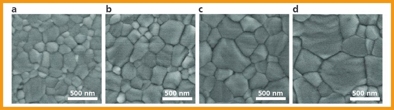
The crystallinity of the cell is also important to investigate as determining the average size of the crystal grains will give an estimate of the number of grain boundaries and similar defects that exist that could interfere with the motion of charges before they reach the transport layers. To quantify grain boundaries, standard optical and electron microscopy (with associated sample preparation such as cleaving and gold-coating) are tried and true methods but are ultimately slow and labour-intensive. Some research has suggested that X-Ray Diffraction can also be used to determine crystal grain size.
To quickly determine if there have been faults in production, such as delaminations between layers, for example, you need a process that can create a reliable signal (instead of relying on a trained observer) such as photoluminescence imaging.
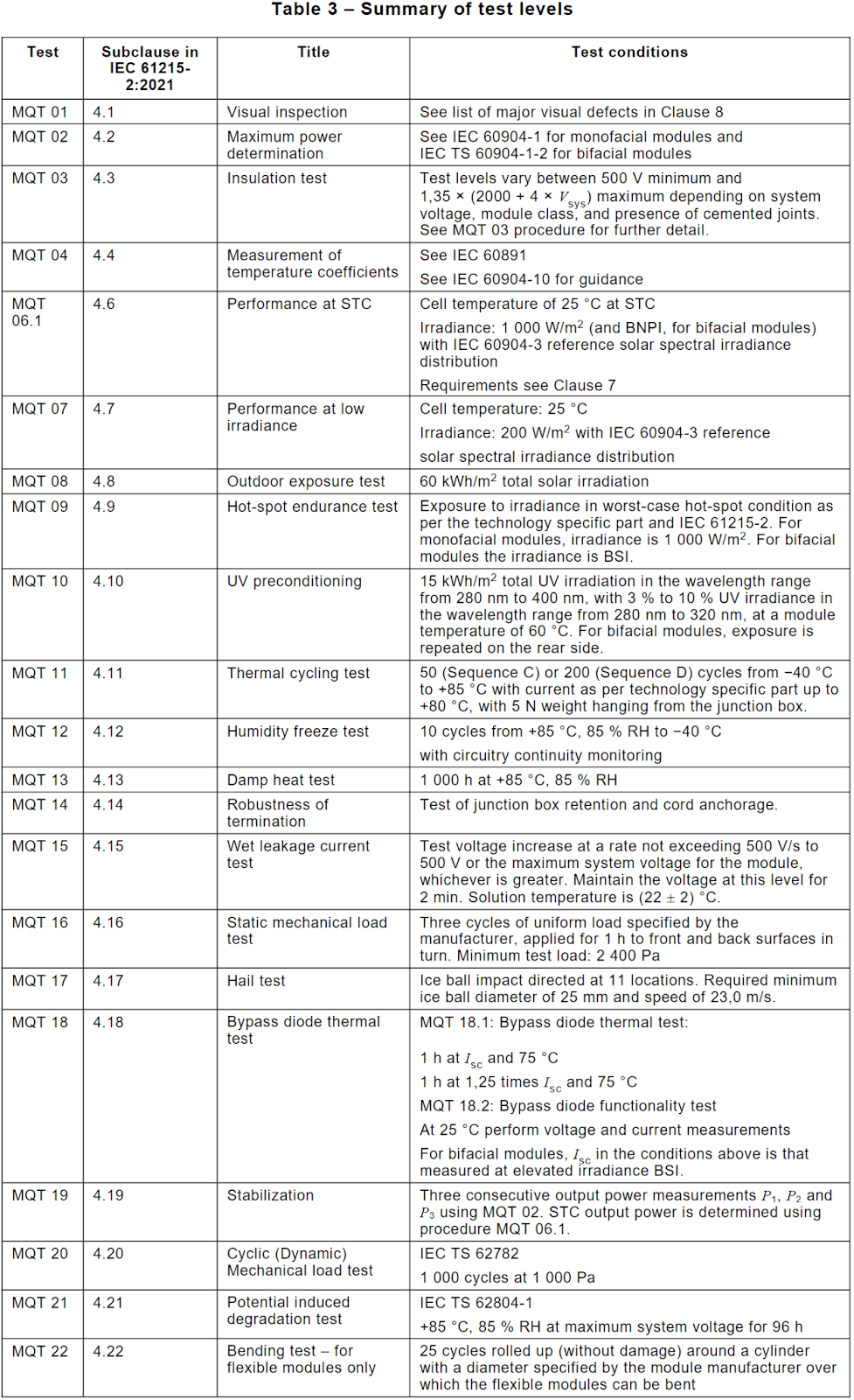
But these types of investigations are more generally confined to laboratory settings and early prototype evaluations. When attempting to determine if a specific solar technology is ready for commercialization, the requirements for testing are significantly more involved. The current international regulatory standard for terrestrial solar devices is IEC 61215-2:2021, and it covers all of the requirements for a panel to be considered acceptable as a commercial device.
This standard requires testing and passing of a solar panel through several sets of tests to validate its behaviour and ability to operate even under non-optimal conditions. These tests and their conditions are collected in Table 3 from the IEC standard.
Suffice it to say, commercializing a solar panel, let alone an entirely new technology such as perovskites, is not a simple endeavour. Especially since Perovskites exhibit behaviours and phenomena that are noticeably different from more traditional solar technologies. These differences grant some benefits, but also impose some limits that require careful consideration about how to reach let alone break.. Explore these in the next chapter, about the limits of Perovskite Solar Cell Efficiency.