The Limit of Single Junction Solar Cell
So far, we’ve only talked about single junction diodes, where there is only one pair of n-type and p-type semiconductors. There is an important fundamental limit to the efficiency of this type of solar cell, known as the Shockley-Queisser limit.
To understand this limit, we have to go back to the beginning of the twentieth century when a scientist named Max Planck produced a law for emitted radiation. Specifically, he produced an equation for the light emitted by what’s known as a black body, which absorbs all of the light we shine on it. The physics behind this is that every atom in the universe is in motion, and as a result of that motion, some light is emitted, even if it’s a tiny amount.
Planck’s equation (now known as Planck’s Law) described the power of light emitted by a black body (per unit area, per frequency). Black body emission varies with temperature.
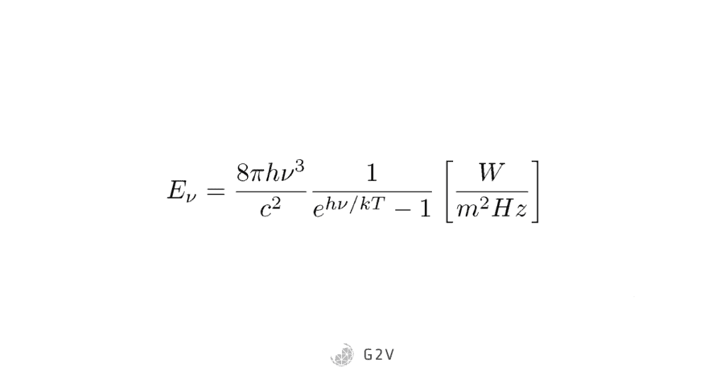
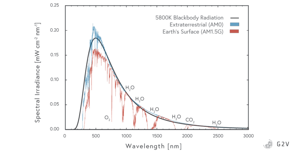
It turns out that a black body of 5800 K is a really good way of modelling our sun’s spectral emission, as you can see below when we plot the above equation against wavelength.
What Shockley and Queisser did was to make use of this model to calculate how much energy we can hope to squeeze from the sun shining on a photovoltaic cell. We’ll go through a quick description of their calculation in order to understand how realistic and important the limit really is, and the role it plays in guiding modern developments.
First of all, they assumed that all photons (particles of light) with energy greater than the band gap will create a free electron. This is an assumption that makes their calculation an upper limit, because they’re starting by absorbing all light that meets the band gap requirement. In most cases any extra energy above the band gap is lost as heat.
By adding up all the photons with energy greater than the bandgap, assuming each one creates an electron-hole pair, then comparing that to the total power incident on a solar cell, Shockley and Queisser could come up with the best-case scenario for how efficient a solar cell could be.
– For Advanced Users –
Here are some more in-depth details about Shockley and Queisser’s calculations.
They started by calculating the number of photons of energy greater than the band gap, that are shining on a given area in a second. Because each photon has an energy E = hv, we just divide that out from Planck’s equation, then add up all the contributions of energies higher than the band gap:
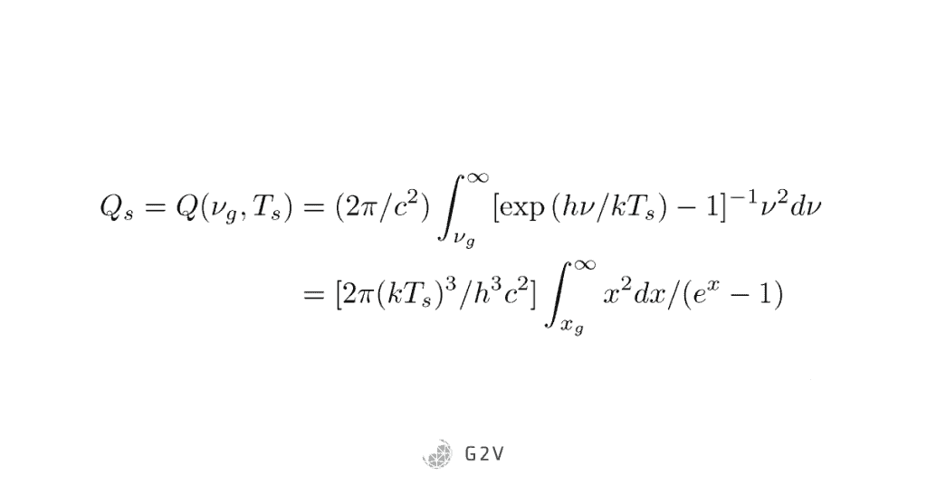
Shockley paper
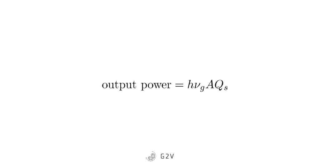
The total power we can get out, assuming all of this absorbed energy is converted into electricity, is this number of photons multiplied by the area we’re interested in, multiplied by how much energy each of those photons is carrying:
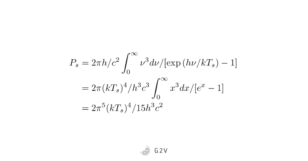
The last step we need is to compare our output to what was put in. For the incident power, all we do is take Planck’s law and sum up all the contributions over the spectrum:
If we divide output power by input power, we get efficiency:
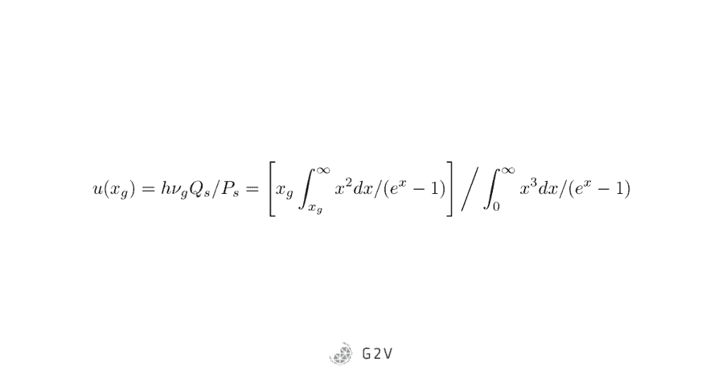
This equation might look intimidating, but the important thing is its shape, and where the efficiency is maximized.
The graph below gives us both those things.
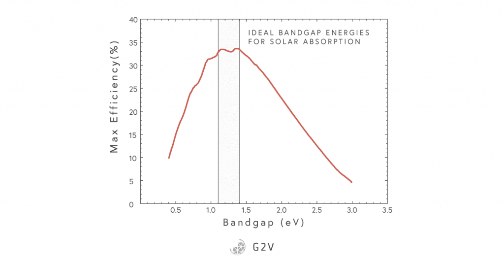
Image Source: By Sbyrnes321 – Own work, Public Domain
We can see that the maximum efficiency is around 32-33%, and happens for band gaps between 1.1 and 1.4 eV. This is specific to our sun as a black body of 5800 K. You might remember that the band gap of silicon is 1.11 eV, which falls within this ideal region, holding a maximum theoretical efficiency of about 32%. As the first industrial solar cell material, silicon is, in fact, a really good choice.
Shockley and Queisser did further calculations to improve the realism of their model. They considered radiative recombination, which is when electrons and holes recombine and produce light. They considered black body radiation from the device itself resulting in some losses. They also talked about the importance of incident angle of sunlight, as well as the resistance across the output terminal that results in the most useful electricity compared to heat losses. Finally, they also considered that not all of the light will actually create electron-hole pairs. This is because of the charge recombination we mentioned above, but also because some materials like silicon have to vibrate a certain way in order for light to be absorbed, so only a cross-section of the light with sufficient energy will actually generate hole-pairs. Also, not all of the junction voltage will be gained by the electrons – some of it will be converted to heat as the charge carriers try to make their way out of the depletion region.
To really measure and quantify these effects for different solar cells, sophisticated physical models need to be paired with the right experimental measurements.
Advanced solar simulators, combined with an IV measuring instrument, allow researchers to get the data they need to understand how effects like the above are influencing their solar cell designs.
Research on modern solar cells focuses on many of the issues that Shockley and Queisser discussed in their seminal paper, as well as trying to find ways to “hack” the limit they calculated.
Some other practical considerations include reflection off the front surface or metal terminals. For example, the calculation they did was for a single-junction solar cell of a single material (one pair of n-type and p-type semiconductors). One way to improve things is to use multiple materials with multiple junctions, which has resulted in a lot of different so-called multi-junction solar cell designs.
Solar Cell Design
Solar Cell Design Goals
We’ve already talked about a few of the goals engineers and scientists have in mind when designing solar cells, and it’s worth mentioning a few more in order to understand the direction of research and device evolution.
The first main goal of solar cell design is to increase absorption, to get more energy out of each cell. We’ve already mentioned a few of the challenges and limits around this goal. Other things that we want to maximize are charge separation and transport, which means keeping the charges apart until they’ve done what they’re intended to do, as well as maximizing the photovoltage, which, as we’ve discussed already, means that each electron will have a higher energy, and you’ll need less solar cells to do useful work.
The next design goals are closely related to the above, and arise from overcoming unwanted effects that take place in the solar cell. One of these is called surface recombination, where the electric charge carriers reach the surface of the device, and instead of traveling around the circuit where they’re intended, each electron-hole pair comes back together and recombines.
Part of the reason this occurs is that just above the surface of a device, the junction potential doesn’t really exist, so charge carriers are free to take whichever path is easiest to recombine.
A final design goal is to improve solar cell production techniques so that we can mass-produce them more cheaply and offer this source of energy to a wider portion of humanity.
Evolution of Solar Cell Design
After the first solar cell was created in 1954, one of the next big advances in design happened in the 1980s, with the development of so-called black cells. These solar cells increased absorption by lowering the amount of reflected light. They accomplished this by texturing the surface of the solar cell, which is a way of gradually transitioning between air and the solar cell material, minimizing the drastic boundary changes that result in high-amplitude reflections.
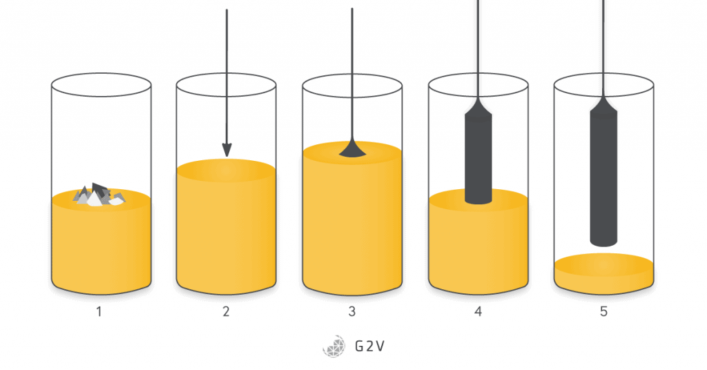
In the early beginnings of the solar cell industry, the main method for producing silicon crystals was via the Czochralski process, where a single crystal is drawn slowly out of a molten melt.
Another method that was much more expensive was the float process, where a single crystal is gradually formed from an existing many-crystal (polycrystalline) rod by moving a molten zone through it and allowing the crystals to join and align.
Also in the 1980s, solar cells were made with silicon dioxide (SiO2) on the front surface, which served as a barrier to prevent carriers from reaching the surface and recombining prematurely.
Because this technique also allowed silicon to have a natural layer of protection from the elements, it became more commercially worthwhile to make solar cells out of the float process, which produced better quality silicon with charge carriers that could travel much farther. With this technique, silicon cells achieved 20% efficiency in 1985.
Another technique to increase absorption was to minimize the area covered by the metal contacts. The metal used to complete the circuit of a solar cell has to attach to the front and back surfaces. Use of point contacts reduces the shadowing of this metal, and results in an increased absorption. This technique allowed Stanford to achieve 22% efficiency in 1992.
Later, it was realized that point contacts at the rear of the solar cell actually help to prevent recombination at the back of the cell, because the silicon to silicon dioxide interface was easier to produce without defects, compared to the silicon to metal interface. This technique, along with a few other refinements, pushed silicon solar cell efficiency up to 24% in 1994.
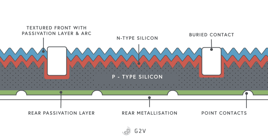
A schematic of a solar cell employing many of these techniques is shown below. Other techniques abound in the field of photovoltaic design and development. Another such one to reduce shadowing is to bury the metal contacts in the semiconductor material. Another approach to reduce surface recombination at the back surface of a solar cell is to have a heavily doped layer that produces a different kind of junction: a p+-p junction. This is a barrier to electrons that might be produced there, but that we don’t want unless they’re coming around from the other side (and have already flowed through our load).
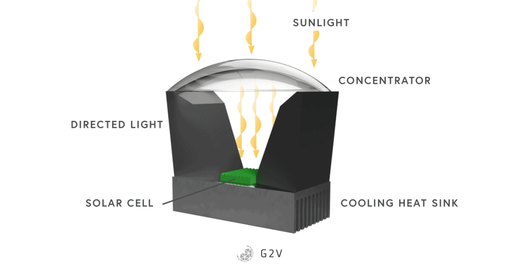
A final technique worth mentioning is called solar concentration (in concentrator photovoltaic cells), where collecting optics focus light onto solar cells. The reasoning behind this approach is that solar cells are more costly to manufacture compared to lenses, so having a smaller footprint of solar cells is worth investigating. However, in practice, it is very difficult to compete with the steady decrease in the price of full-footprint silicon solar cells.
What are Multi-Junction Solar Cells?
All of the design methods and progress we’ve discussed so far have centered on silicon and a single junction solar cells. As you might imagine, there’s no law saying that we have to stick with silicon, nor do we have to stick to a single junction solar cell! We’ll talk about alternative materials in the next section (because there’s a lot of ground to cover there), but the multi-junction solar cell approach is a general design concept that is pretty easy to understand.
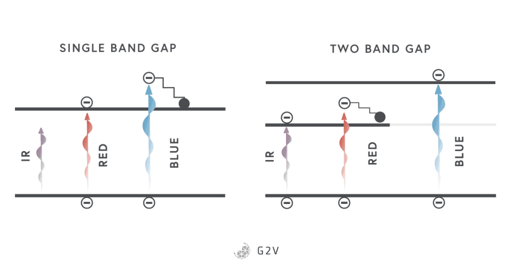
When we were calculating the maximum efficiency of solar cells, we said that a photon with energy greater than the band gap would move a single electron into the conduction band. Any excess energy is mostly converted into heat. That means that all of the sunlight with energy greater than the band gap is not being absorbed very efficiently.
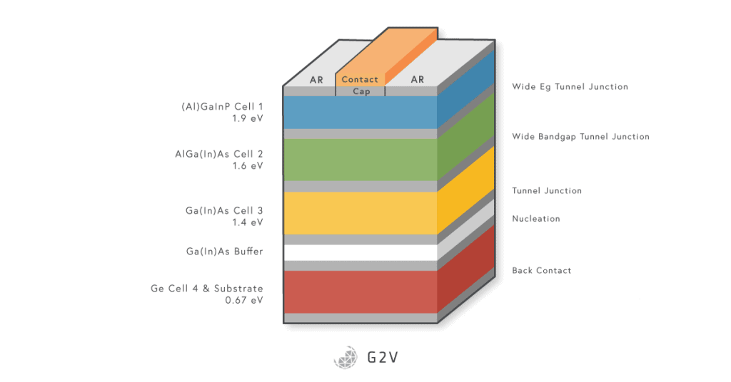
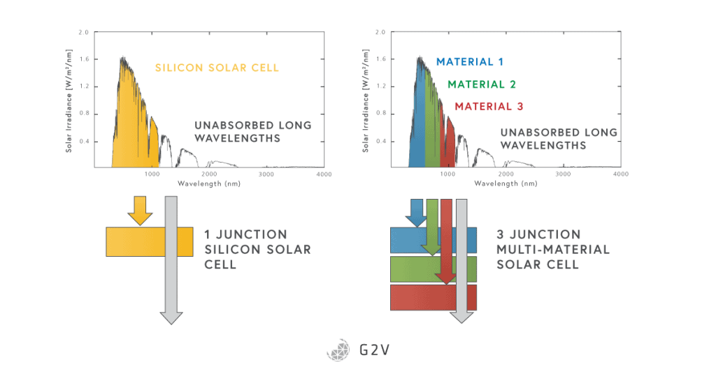
The multi-junction solar cell tries to rectify this inefficiency by presenting multiple band gaps to the incoming sunlight. Basically, it presents a series of materials and junctions to the light, usually starting with the highest energy (shortest wavelength) light at the top of a stack, and working down to the lowest energy (longest wavelength) at the bottom.
While the greatest power could be extracted from a multi-junction solar cell if each junction could be optimized independently (and therefore part of its own electrical circuit), this isn’t really practical, and usually the stack has contacts at the top and bottom, and none in the middle. This means that the performance is somewhat constrained because, for example, the currents from each cell have to match one another.
However, multi-junction solar cells allow us to absorb much more of the solar spectrum, with record efficiencies up to 39%. The number of junctions so far has included two-junction, triple-junction, four-junction, five-junction and six-junction solar cells. Multi-junction solar cells are sometimes called tandem cells, usually when they consist of two materials with very different band gaps.
One of the disadvantages and limits of multi-junction solar cells is that the carriers have to diffuse out to the metal contacts, which limits having a huge stack of junctions. To get around this, some designers have made use of quantum tunneling to create tunnel junctions and allow the carriers to get out to the metal contacts by non-classical means (it’s not quite teleportation, but it’s pretty close).