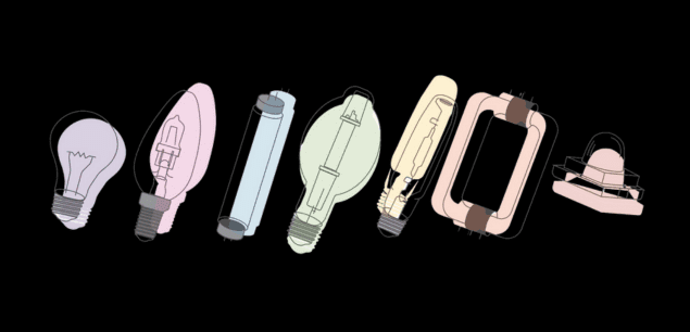
If you are interested in learning more about the history of LED solar simulators, the “The Road to LED Solar Simulator” chapter on YouTube will provide more in-depth knowledge. For the entire history of solar simulation, keep reading.
What is Solar Simulation?
The main objective of the solar simulation field is to produce illumination that approximates natural sunlight, providing a controllable indoor test facility under laboratory conditions. Industry standards were required to achieve this.
The Standardization of Artificial Sunlight
Solar simulators aim to mimic sunlight by artificial means. For them to do this reliably and consistently, international standards needed to be defined.
This was done in a set of workshops in 1975 and 1977 sponsored by ERDA and NASA. They published a report on standard terrestrial solar cell measurement procedures, including detailed descriptions of standard solar simulators. During these workshops, scientists averaged the observable sun intensity and spectrum and agreed on a baseline.
In this report, the standard solar irradiance was chosen to be 1000 watts per square meter (W/m2), and an air mass of AM1.5 Global was chosen as the spectral composition to represent sunlight on Earth.
Here is a recap of Air Mass (AM1.5) and solar irradiance if you missed our previous chapters.
Both of these standards (for intensity and spectral composition) were incorporated into ASTM standards (such as ASTM E927, ASTM G173-03, and ASTM E490) and many other international standards (such as IEC 60904-9 and JIC C8912). These standards validate and qualify solar simulators and define a common ground around sunlight.
The answer to the questions “What is sunlight?” and “How much sun do we get?” is that standard sunlight has an irradiance of 1000 W/m2 and a spectral distribution matching AM1.5G.
The standard AM1.5G spectrum can be seen below:
The groundwork from ERDA and NASA accelerated the work on the solar simulator, aka Engineered Sunlight, which would be the primary instrument used in the solar simulation field.
Solar Simulators: Engineered Sunlight
Solar simulators are devices whose light source offers similar intensity and spectral composition to natural sunlight. They are scientific equipment used to replicate sunlight in controlled laboratory environments. Solar simulators (also called “sunlight simulators” or “sun simulators”) are essential for the research and testing of products and processes that either use or are affected by sunlight, such as solar cells, photochemical reactions, aerospace applications, materials testing, and other photo-reliant applications.
There are two approaches to producing “artificial sunlight”:
- subtractive: take a broad spectra light source and filter/use optics to reduce the spectra to something more closely matching sunlight, and additional processing to increase uniformity
- take narrow-band light sources and add them together to create the desired spectra (and use optics to increase uniformity).
Because artificial light and sunlight are generated differently, additional steps are necessary to match both sunlight’s intensity and spectral composition. These two methods of creating artificial sunlight didn’t happen overnight.
History of Solar Simulators
Indoor solar simulation started at the beginning of the 1960s with a series of research programs sponsored by NASA.
These programs aimed to develop a ground test facility to simulate the space environment for testing Earth satellites and other spacecraft. The chamber for this testing was named the “Space Environment Test Chamber,” and a solar simulator was used to simulate space solar radiation.
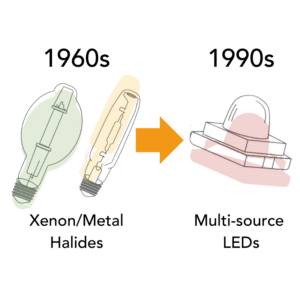
After testing and comparing, a mercury Xenon lamp was chosen as the best light source. Jet Propulsion Laboratory (JPL) NASA created a series of several large solar simulators to meet the increasing test requirement for space technology.
In 1986, the European Space Agency (ESA) created a solar simulator to meet the European space plan. The ESA solar simulator was larger and had a simpler optical setup than JPL. Later, Russia, South Korea, and Japan constructed their own large-scale solar simulators.
These space solar simulators paved the way for much of today’s fundamental research and testing for solar simulation.
Solar simulators are needed to provide a common basis for comparing solar devices and designing large arrays. The industry needs to test solar cells and other devices under controlled conditions, thus creating a need for accessible solar simulators.
Several companies such as Hoffman Electronics Corp. (using a combination of Xenon arc lamps and tungsten bulbs), Optical Coating Laboratory (modifying light sources via optical filters) along with Spectrolab X25 were some of the pioneers of standard solar simulator design and manufacturing.
Then, in the 1970s, due to the photovoltaic industry’s development, a standard measuring method became necessary. Early in the development of photovoltaic (PV) cells, the performance was tested with light sources that needed to be continually calibrated by using expensive large-scale space simulator chambers. A standard was essential to determine the performance of samples from a single source, to compare samples of different designs, to study changes in device performance as a function of time, and to provide system design data to engineers and marketing. Because of this, the first solar cell standard procedure was set in 1975 and updated in 1977.
In 1978, the Subcommittee on Photovoltaic Electric Power Systems of ASTM Committee E-44 started developing standard methods for measuring the electrical performance of photovoltaic devices. In 1985, a series of revised ASTM standards was finally available.
Solar simulators are fundamental for photovoltaic measurements being done in both research and industry, and since the illuminated current vs. voltage (I-V) is sensitive to the spectrum, intensity, and temperature, looking for new light sources and developing higher accuracy optical systems based on the leading standards became a priority.
Additionally, standard PV solar simulators had issues with lowering the average power and temperature fluctuations (caused by prolonged exposure to the light). As solar cell manufacturers started to ramp up manufacturing, large-area simulators capable of testing modules were developed. The illumination times were reduced to minimize power use and excessive heat generation, decreasing the measurement time. As a result of trying to solve this issue, the pulsed solar simulators were designed and developed.
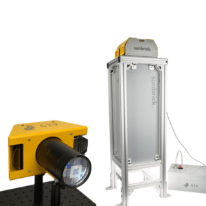
In parallel, additional solar simulator development continued, including multisource simulators for improved accuracy, high-intensity simulators for multijunction and concentrator systems, and LED systems. With the development of high-power LED technology in the 1990s, solar simulators were developed to use this new light source, which offered advantages such as tunable spectra, high accuracy, long operating life, and output control of the light source with a 30- 50 nm resolution. LEDs consume less energy, pack much smaller than conventional lamp-based housing, and can be controlled within microseconds or operated stably at one light output intensity continuously for a long time.


