Chapter 7
We’ve covered a lot of material as far as how solar cells work, and what their operation depends on. While it can seem quite daunting to try and dream up a test that captures all of the various factors we’ve discussed, the key information we need can be found in a few graphs/parameters:
- Responsivity
- External Quantum Efficiency (EQE)
- IV response
- Efficiency
The first three graphs are what we need to calculate the overall solar cell efficiency, and we’ve already introduced all of the quantities above. Essentially, what we’re after is how the solar cell responds to different wavelengths (which is given by the responsivity and EQE), as well as how it responds under different electrical conditions (which is given by the IV response). So how do we conduct tests to measure each of these things?
Because the photovoltaic industry is so large and active, there are actually standard test methods for measuring parameters of photovoltaic devices. We won’t go into great detail as far as what the tests involve, but it’s worth outlining the key elements of the tests, as well as how they’re typically done in practice.
Measuring Solar Cell Responsivity
A schematic of a typical setup (taken from the ASTM E1021-15 standard) is shown below. We start with a broadband light source, meaning one emitting a wide range of wavelengths. In order to not be as heavily influenced by dark current and give a more accurate snapshot of the device under its intended working conditions, a bias white light (which is also broadband) is shone separately onto the solar cell. Now, we want to do two things: measure the response at a particular wavelength, and separate the effect of our bias light from the light that we’re varying. Two pieces of equipment allow us to achieve this. We add a chopper so that there’s a pulsed response on our device through which we can easily tell what’s coming from the bias light or the inspection light. We also add what’s known as a monochromator, which picks out a specific wavelength of light to be used for inspection. After that, the rest of the details of the measurement are concerned with getting accurate numbers for the power, and comparing against a known reference.
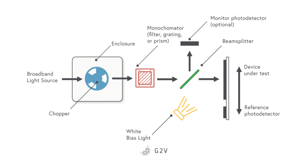
With the monitoring photodetector, we know how much optical power we’re shining on the device. We can measure the output electrical current, so we now know the two quantities we need to calculate the responsivity at each wavelength.
There are subtle variations to how the responsivity is measured, with different strategies improving all the time. As long as a new method can be shown to be equivalent to the standard test, it’s just as valid. At G2V, we have software representations of many of the experimental elements described in this section, which allow us to calculate device responsivity without the use of additional hardware beyond our solar simulators. Contact us if you’d like to know more about how we do this, and whether it might be suitable for your needs.
Measuring External Quantum Efficiency (EQE) of a Solar Cell
Once you’ve gotten responsivity through the test described above, the EQE is really easy to calculate. We’ve already seen the equation that allows us to do this:
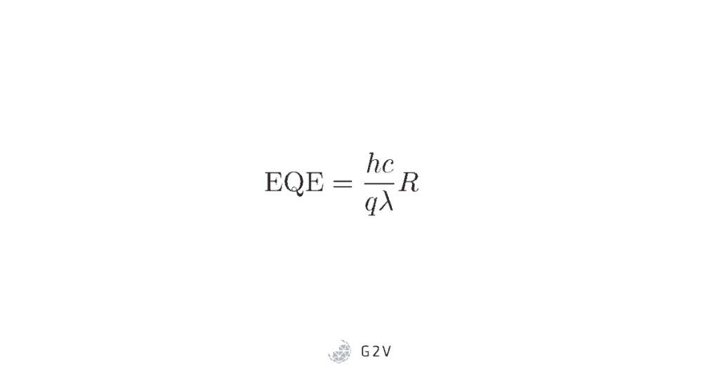
Where h is Planck’s constant, c is the speed of light, q is the charge of the electron, ƛ is the wavelength of light, and R is the responsivity we obtained through the test in the previous section.
Measuring IV Characteristics of a Solar Cells
It turns out that, using the method described above for measuring responsivity, we also get enough information to calculate the total current out of the device. However, a much more practical method is to measure the current and voltage response of the device under broadband light, which removes the need to manually integrate (sum) all the individual pieces. IEC 60904-1 specifies the standard procedure for measuring current and voltage characteristics of photovoltaic devices. More specifically, ASTM E1036-15 specifies the test methods for photovoltaic modules using reference cells, which we’ll summarize here.
For reference,IEC 60904-3 specifies how to go about relating the results to a standard solar reference spectra such as AM0 or AM1.5G. Even if you don’t carry out the measurements under the exact conditions required by the standards, IEC 60891 specifies the methods you can use to translate your results into an acceptable format.
In essence, the test of IV response seeks to measure, at the bare minimum, the following parameters of the solar cell, which we defined earlier in the max power section.
- Short-circuit current, Isc
- Open-circuit voltage, Voc
- Current at maximum power, Im
- The voltage at maximum power, Vm
Usually, a device under test (DUT) is compared against a reference photovoltaic cell of known response that was calibrated against the same target spectrum (requirements for reference cells can be found in ASTM E1040. The DUT is supposed to match the spectral response of the reference cell to within 5%, and the solar simulator used has to meet the standards specified by ASTM E927.
The temperature of the device needs to be measured, along with the voltage and current using a four-wire measurement from Kelvin probes, which we’ll describe below.
Four-wire Measurements of Resistance and Current
When trying to measure the voltage across and current through a device, we are always limited by how much resistance is introduced by the wires doing the measurement. However, there is a way to eliminate this source of error by using what’s called a four-wire measurement.
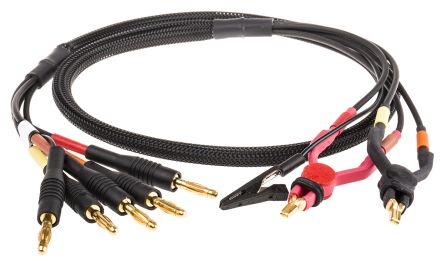
A four-wire measurement is a combination of a voltmeter (measuring voltage) and an ammeter (measuring current). Another name for four-wire probes is Kelvin probes. In a Kelvin probe, there are two clips for current, and two for voltage. They’re isolated so that current from the ammeter side doesn’t pass into the probes from the voltmeter side.
Kelvin probes need to be hooked up to a system that allows for some iteration on the target voltage or current. What does this mean? It means a system that allows many attempts to try and get the target current, and that can source or sink current as needed. Let’s say we want to apply 100 mA of current at 2V. However, when we try to do this, we find that we get a 2.2 V drop across the device at a current of 90 mA. This is because of the resistance introduced by the probes themselves. Therefore, we adjust the current or voltage one way or another to get closer to our target (which is why we need a system that can source or sink current). Because we’ve got two probes, we can do this somewhat independently, until we get close enough to the target to record a measurement.
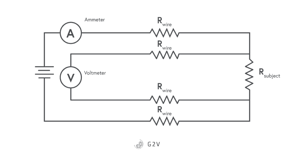
The idea behind a Kelvin probe is that the voltage probes carry insignificant amounts of current, meaning that the voltage drop in those wires is minimized (or negligible). The current measurement is the same at all points in a series loop, so the current measurement is fine as-is. The relationship between the two might need to be adjusted for the resistances of the wires, as in the example we described above, but overall the four-wire measurement is a way to accurately get current and voltage information of a device.
A Kelvin or four-wire measurement is essential to getting accurate IV data while testing a solar cell.
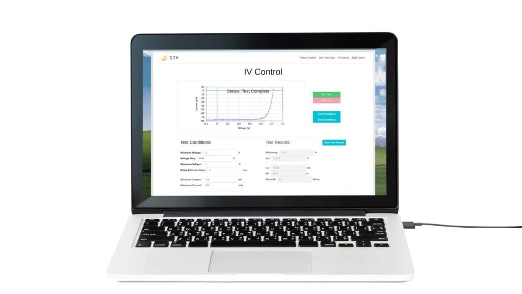
A variable load is applied across the four wires in order to get a variety of current and voltage measurements for the device under test. Exactly what current and voltage is unknown until tested, which is why there is some iteration needed. As long as you can measure what the current and voltage are through those four wires, you should then have the information needed to generate the IV characteristic curve of the device under test.
The short-circuit current Isc will occur at V=0, and the open-circuit voltage Voc will occur at I=0. That’s two of the four parameters. To get the maximum power, the current needs to be multiplied by the voltage to get power, which can then be examined to find out the peak location of Im and Vm.
G2V offers an optional IV card add-on to its solar simulators, which comes with a Kelvin probe to make these four-wire measurements. Additionally, we offer calibrated and tested reference cells do to the tests described above. Contact us for more information to find out if our devices are a good match for your testing needs.
Measuring Solar Cell Efficiency
If we rearrange the efficiency equation from earlier, we see that we can calculate the efficiency as soon as we know the maximum power point, and the incident power:
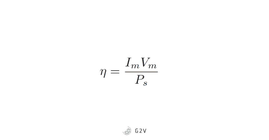
One thing to be careful of is that the power has to be the total power on the cell. Alternatively, you can use the form where we’re using power densities and current densities:
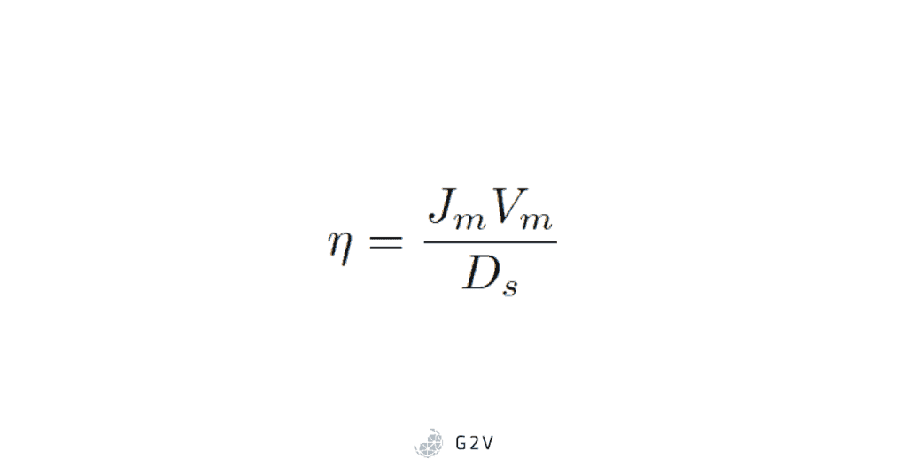
Where in this case Ds is the power density (or intensity) of the sun’s irradiance, and Jm the maximum current density (current divided by area). The exact measurement of area of a solar cell is also open to debate, but for now we’ll leave those details to others.
Standardized Tests of Solar Cells
Because there is a great deal of work both commercial and academic in the field of photovoltaics, there is also a great need for standardization of the methods and means of comparing one device to another. NREL has done an impressive job of externally validating solar cell devices, and tabulating the data to apply even and fair metrics to a variety of devices. Any claims for world record device efficiencies are effectively put to the test at NREL. As the field continues to evolve, they’ve kept up with the demands of the industry, adjusting their test methods to fit new device requirements.
Some research groups are interested in device response to non-standard spectra, particularly because certain materials have optimum conditions for certain measurements, that might change dwell time, speed, etc. They, therefore, might want the ability to fine-tune the spectrum illuminating their device under test. LED-based solar simulators are perfect for this sort of spectral tuning and combined with our available reference cells and IV modules can equip researchers with the tools they need to carry out tests at and beyond the standard. We can even simulate solar spectra based on your geographic location—ask us how!
The above standard tests are fairly straightforward and leave little room for interpretation when it comes to determination of the solar cell parameters. However, as we’ve discussed, there are other physical effects at play. We’ve seen different models that account for these effects through, for example, shunt resistance, series resistance, and a recombination diode. Quantifying these other parameters can be very useful for researchers to know whether they’ve improved, for example, recombination effects, or reduced the number of defects, etc. To quantify these parameters, however, is a much more difficult task, which requires more sophisticated models, mathematics and methods, the subject of the next section.
Next Chapter 8: Parameter Estimation Methods