
Solar Simulation Guide
Many industries require testing using light similar to the sun. But have you ever wondered what goes into this world of simulating light?
Our comprehensive guide to solar simulation explores everything from the science of sunlight, air mass spectrums, solar simulators, the classification to compare solar simulators, and many other topics.
Grab a snack and dive into our 17000+ word article broken into multiple chapters to learn about Solar Simulation! To assist in learning about the field of solar simulators, we will also include links to the various chapters from our Solar Simulation and LEDs: Multi-Source Lighting for Advancing Future Technologies video on YouTube.
What is Solar Simulation?
To produce illumination approximating natural sunlight to provide a controllable indoor test facility under laboratory conditions. A more in-depth way to think about this is by asking the Why question.
Why Does Solar Simulation Matter?
Our answer is simple. Take a moment and think of everything light touches—go ahead, we can wait. Now ask yourself this: How do you accurately test and advance the fields of science and manufacturing if you can’t accurately test?
That is the true birthplace of solar simulation—the need for accurate and repeatable testing.
This is why we dedicated a series of articles to begin laying out the field of solar simulation.
Solar Simulation Comprehensive Guide Table of Contents
If you are new to the field of solar simulation, we recommend starting with Chapter One. For those who have a good grasp of what goes into solar simulation, jump to the section that interests you or that you require more information on.
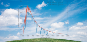 Chapter 1: The Solar & Molecular Absorption Earth’s sun, like the solar system, is the central theme of our Solar Simulation article. Understanding the fundamentals of sunlight is the starting point for this article. Learn more about our sun and what sunlight is, and get a brief overview of the solar spectrum! |
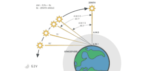 Chapter 2: Air Mass Spectrum Overview We explore Air Mass (AM), the various Air Mass Spectrums found, and a breakdown of the various spectrums used in research. Explore this and learn more! If you want more information on the more common spectrums AM0 and AM1.5, head to chapters 3 and 4. |
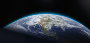 Chapter 3: Aerospace and the AM0 Spectrum Light is being sent even in the vast darkness of space between the Sun and Earth. Knowledge of the AM0 spectrum is critical for those exploring the cosmos. This chapter examines the AM0 spectrum and its nuances for those interested in Aerospace light. |
|
Chapter 4: Terrestrial Light and The Varying AM1.5 Spectrum Earth’s light spectrum isn’t as simple as AM0 with one spectrum. Researchers require varying degrees, such as AM1.5, AM1.5G, and AM1.5D. We explore the differences in each and add a small comparison table at the end! Learn about the difference between the AM1.5 spectrums. |
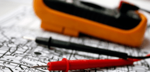
 Chapter 5: The Fundamentals of Measuring Light We explore the differences between radiometry and photometry, the units of measurement for each of them, and how frequently they are used. We summarize this section in a handy chart for quick reference! |
Chapter 6: The History of Solar Simulators This chapter takes a quick detour back to the 1960s to explore the definition of a solar simulator and how it came to be. If you love history and the advancement of technology in the solar testing space, this chapter was created for you. |
|
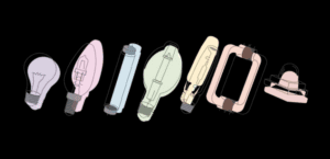
Chapter 7: Solar Simulator Design & Components Solar simulators can be broken into three simple components: light source, power supply, and optics. We explore each of these components of a solar simulator design. |
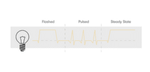
Chapter 8: Exploring Flashed, Pulsed, and Steady-State Solar Simulators Solar Simulators fall into three primary categories: flash, pulsed, and steady-state. We explore the nuances between the three and explore the future of a potential fourth category. Come explore this section and learn about the differences and similarities.
|
Chapter 9: IEC 60904-9:2020 Gold Standards of Solar Simulator Classification Explore the Class AAA standard that governs Solar Simulators. This section gives a quick overview of the 3 updated criteria for Spectral match, Spectral Uniformity, and Spectral Stability and also explores the new criteria added in 2020, Spectral Coverage and Spectral Deviation. |

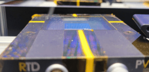
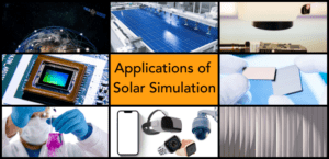 Chapter 10: Where Are Solar Simulators Used? Common scientific fields that use solar simulators are Photovoltaics, Photochemistry, and Aerospace, to name a few. This section gives you quick links to dedicated pages across our site to the various scientific fields for solar simulators. |
 Chapter 11: Solar Simulation FAQS This is a supplementary chapter of the solar simulator article. Here, we have consolidated all the common questions we have received in the field. We are continuously updating this chapter if you have a question we missed. |
|