
Chapter 9
Frequently Asked Questions about Solar Cells:
How Do You Test Solar Cells?
Testing solar cells is usually done to figure out one or more of the following:
- Responsivity: how much electrical current we get out of the solar cell compared to the optical power put in. This is specific to the wavelength or colour of light, and is usually plotted as a curve. This is usually carried out with a broadband light source put through a chopper (so that its contribution can be easily seen on a detector) as well as a monochromator that allows for the wavelength of light to be selected and scanned. Finally, a white bias light (usually a solar simulator) illuminates the sample to ensure the performance is being measured under conditions of sunlight. For more information, see measuring solar cell responsivity
- External Quantum Efficiency: the ratio of charge carriers out compared to the photons (particles of light) shining on a material. This can be calculated from the responsivity. For more information, see measuring EQE.
- IV Response: The current (I) and voltage (V) characteristics of a solar cell allow researchers to know the settings for which the maximum power will be achieved. This is usually done using a four-wire Kelvin probe, where the current can be measured separately from the voltage so that the resistance of the probes themselves doesn’t impact the test. A series of voltages are applied, and then the current the solar cell can generate is measured, ultimately producing an IV response curve. For more information, see measuring iv characteristics of a solar cell.
- Efficiency: This is a measure of how well the solar cell converts sunlight into energy and can be calculated using the following equation. Note that this requires knowledge of the maximum power point, which means the IV response has to be measured first.
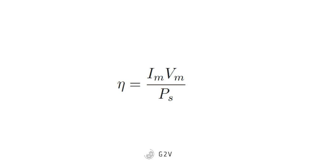
Im is the current at maximum power, Vm is the voltage at maximum power, and Ps is the power of sunlight shining on the cell. For more information see measuring solar cell efficiency.
Sometimes, manufacturers or researchers want to estimate the circuit model parameters of their solar cells, which requires additional steps beyond what’s described above. For more information, see PV solar cell models.
How Do You Test Monocrystaline Solar Cells?
Because monocrystalline solar cells are the most common, the test methods described above were practically written with these in mind, so the process is the same.
The key is to the testing is that the measured IV response has to span the full range of the device under test (DUT). In other words, whatever system you have for applying voltage during your four-wire test needs to be capable of the full voltage range. In addition, the measured current output needs to be capable of syncing the full current output by the DUT. What those ranges will vary considerably depending on the device manufacturer, source material, and solar cell size.
How Do You Test Perovskite Solar Cells?
Again, the test methods described above apply to any type of solar cell. What will differ in each case is the IV characteristic curve.
The key to the testing is that the measured IV response test has to span the full range of the device under test (DUT). In other words, whatever system you have for applying voltage during your four-wire test needs to be capable of the full voltage range. In addition, the measured current output needs to be capable of syncing the full current output by the DUT. What those ranges will vary considerably depending on the device manufacturer, source material, and solar cell size.
How Do You Test Solar Cells Using Lights?
See the first FAQ for the full method. The results of a given solar cell test will be more accurate if a higher-quality solar simulator is used, because it better represents full-spectrum sunlight, meaning that the data will be more representative of its performance under real-life conditions.
How Do You Perform an IV Curve Test?
Usually voltage and current are measured using a four-wire Kelvin probe, which allows for both current and voltage to be measured independently, without their resistance impacting the actual measurement. This is because there is a separate path for the current to flow (through the ammeter or current-measuring probes), minimizing the current through the voltage probes and thus minimizing the voltage drop across the resistance of the voltage probes themselves.
Usually, in an IV test, a voltage is applied across a solar cell, and the resulting current the solar cell can generate is measured. This process is repeated for a series of points, and an IV curve is produced.
For more information, see measuring IV characteristics.
When Should You Perform an IV Curve Test?
If you’re researching or manufacturing solar cells, the sooner you can measure the IV parameters, the better. The reason is that from these IV parameters, the overall cell efficiency can be calculated, as well as other parameters like the shunt and series resistances, all of which give indicators of what’s occurring physically inside the device, and how to target efforts toward improvement. For more information about circuit models and what the parameters mean, see How Do solar cells work.
Because the cost of silicon solar cell systems continues to drop (see Swanson’s law graph in “what is photovoltaics” section), it is vital for researchers to get fast and accurate data on their cells so that efforts can be targeted and the transition to market of ground-breaking technologies that can compete with silicon can be expedited. For more information about this interaction of silicon economics and research, see economics of silicon.
How Do You Measure The Charge Carrier Density of Solar Cells?
Charge carrier density is the number of charge carriers per unit volume. This is a quantity not specific to solar cells; it actually applies to any semiconductor. It refers to the number of excess electrons (in an n-type semiconductor) or the number of holes (in a p-type semiconductor).
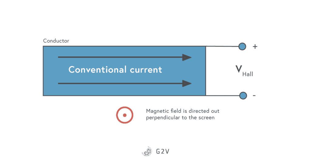
The charge carrier density can usually be measured via the Hall effect. The Hall effect occurs when a magnetic field acts on a flowing current, resulting in a force perpendicular to the direction of movement. The result is a Hall voltage perpendicular to the current flow, as shown below.
A measure of this Hall voltage can be related to the charge carrier density in the following manner:
The Hall voltage produced is equal to
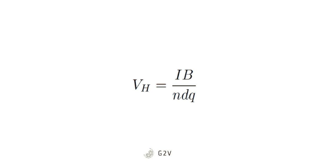
Where I is the current, B is the magnetic field, n is the charge carrier density, d is the sample thickness, and q is the charge of an electron. The above equation can be rearranged for the charge carrier density:
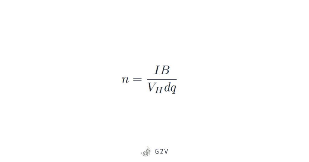
Thus, to determine charge carrier density, you need to:
- Apply a known magnetic field perpendicular to current.
- Measure the current.
- Measure the hall voltage (perpendicular to current flow).
- Measure the thickness.
Then the above equation can be used to calculate the charge carrier density. Note that if there is more than one type of carrier, the charge movement process isn’t quite as simple, and more complex equations will be required. However, the above calculation can be a useful starting point.
How Do You Measure The Current Density of Solar Cells?
The current density is defined as the current per unit area of a solar cell. If you can measure the current, then it’s simply a matter of dividing by the exposed area of the solar cell. Usually, this is measured in mA/cm2. The measurement of the area, however, can be tricky, because you have to be sure to exclude areas that are covered by the front wires of the solar cell, for example, and include or exclude edges as appropriate.
How Do You Test the Efficiency of Solar Cells?
First, you need to know the current (I) and voltage (V) behavior of the solar cell in question, also known as the IV characteristics. The IV characteristics of a solar cell allow researchers to know the settings for which the maximum power will be achieved. This is usually done using a four-wire Kelvin probe, where the current can be measured separately from the voltage so that the resistance of the probes themselves doesn’t impact the test. A series of voltages are applied, and then the current is measured, ultimately producing an IV response curve. For more information, see measuring iv characteristics of a solar cell.
Once you have the IV response curve, you can determine the current (Im) and voltage (Vm) settings which will achieve the maximum output power from the solar cell. The efficiency, which is a measure of how well the solar cell converts sunlight into energy, can then be calculated using the following equation. Note that it also requires knowledge of Ps, the power of the incident sunlight.
For more information see measuring solar cell efficiency.
Why Do We Test Solar Cells In The Dark?
Because every photovoltaic solar cell is fundamentally a semiconductor diode, we can gain insight into the device’s behaviour by comparing, for example, the shape of the current and voltage (IV) curve in the dark to the same curve under illuminated conditions. The illumination can also be a source of noise that introduces uncertainty in the measurement of a solar cell’s diode parameters, so measuring it independently of light can be more accurate. Any differences in diode parameters between illuminated and dark conditions can then be isolated and tracked down efficiently.
One caution is that many dark-versus-illuminated comparisons assume that the two curves are shifted only by the light-generated current, whereas, for example, the contact resistance may be changing in the two cases because the current is flowing in opposite directions.
For more information on different parameters and what they indicate about a solar cell’s internal device physics, see how do solar cells work.
Why Is Silicon The Most Commonly-Used Solar Cell
Silicon can be extracted from sand, which means it is extremely common. It also leverages a lot of the same manufacturing processes that are used for microprocessors and integrated circuits (used in computers and other digital devices, for example). Finally, it has a band gap (energy difference between valence and conduction electrons) that is close to the peak of solar emission, meaning that it will generate electricity from a good portion of the sunlight incident upon it. For more information about alternative materials for solar cells, see an overview of materials used.
Additionally, our IV cards allow for a simultaneous capture and parametric scan of a solar cell, so researchers can quickly characterize their devices and generate standard curves without the need for multiple tools or pieces of software.
Finally, our devices offer an optional ability to measure spectrally resolved responsivity (SRR) – our low-resolution EQE. The SRR unit is capable of measuring the spectral responsivity or quantum efficiency at the LED wavelengths used in the instrument.
This capability can be used to study the behaviour of different absorber materials within your devices, or to measure the performance of different junctions in a multi-junction solar cell.
This additional information can be crucial for evaluating whether a device meets specifications, and where it might need additional development.
If you’re a researcher in this field, contact us to find out more about how our solar simulation products can help you capture the best data about your photovoltaic devices.
Photovoltaics Article Summary
Solar cell materials are deployed at full industrial scale. There is direct contact with the real-world performance. Earlier high quality, accurate measurements in the R&D process will allow
– more efficient use of R&D resources since false starts will be avoided
– accurate feedback at the research phase will help improve processes and materials early, resulting in the development going smoother – fewer surprises mean faster development
As humanity surges into the future, there is a growing demand for energy to increase GDP, improve the quality of life, and reduce infant mortality. There is also a growing need to mitigate emissions contributing to global warming. A multi-pronged solution is needed. Photovoltaic or solar energy technology is a rapidly growing renewable energy source that is expected to play a major part in the energy future of our species. Despite solar energy’s advantages of being clean, portable, and of a high power density, there remain some challenges to maximizing its potential benefits. A better understanding of photovoltaics through fast and accurate research and testing is essential to unlocking the full potential of solar energy.
At its core, a photovoltaic cell a semiconductor diode with a difference between its conduction and valence energy bands that matches the peak energy of incoming sunlight. A particle of light, or photon, can generate an electron-hole pair in a photovoltaic cell. Because of the semiconductor’s junction potential, the electron will travel through an external circuit, and we can in this way generate power from sunlight. This whole process is known as the photovoltaic effect.
The first material used for solar cells was silicon in 1954 and remains the dominant technology today. While silicon’s band gap is nearly ideal for solar absorption, it has an indirect band gap which results in a lower energy absorption coefficient. Also, while the manufacturing techniques for silicon crystal growth have benefited tremendously from the advances in the microcircuit industry, some argue that there are still gains to be had in finding materials with cheaper manufacturing methods.
A variety of alternatives to silicon solar cells exist, including multijunction solar cells that absorb more of the sun’s total light, III-V semiconductors, thin-film solar cells, perovskites, organic solar cells, and graphene. The material science and the way they interact with light are each unique, with ongoing innovations to get the best material characteristics for converting light into electricity.
Because silicon’s cost per watt of energy continues to drop, anyone in photovoltaics research has the difficult challenge of trying to compete with an established low-cost market leader. Therefore, in order for their efforts to be effective, they need fast and accurate data on their devices in development, to avoid false starts and steer in the most efficient directions with the fewest surprises.
G2V’s solar simulators can provide light sources to test photovoltaic devices. In combination with our add-on IV module, a solar cell can be tested and the key circuit model parameters extracted for validating what changes might need to be made. There are a variety of models and approaches available to extract the parameters and represent the physics occurring within the device. We’ve summarized a few of these in the article, including the ones used in our software, but if you have any requests for models you’d like to see implemented, please let us know, and we’ll do our best to put them in with proper attribution.