
Solar simulators are capable of reproducing sunlight under a variety of aerospace-relevant conditions. This article discusses how solar simulators are useful in aerospace photovoltaics (PV) as well as the key solar simulator characteristics to seek, including spectral tunability and output, AM0 capabilities, spectral programmability, integrated software and hardware modules, and flashing capabilities.
Many spacecraft rely on solar power as an energy source for some or all of their operational power requirements. It is most common in Earth orbit, but has also been used as far as NASA’s Juno spacecraft, which is orbiting Jupiter with three 30-feet-long solar panel arrays.
For a great many near-Earth space applications such as CubeSats and Mars rover missions, solar panels and photovoltaic energy play a major role in these enterprises’ success.

Spacecraft in and beyond Earth orbit make ample use of solar radiation as an energy source.
Photovoltaic use in flight isn’t restricted to spacecraft, however. The first solar-powered airplane, Sunrise, flew in 1974. More recently, Airbus’s recent test flights of their Zephyr unmanned aerial vehicle (UAV) demonstrated that a solar-powered aircraft could stay in the air for a week to provide regional Internet access in Arizona.
Even if an aircraft is not entirely solar-powered, solar energy is expected to play an increasingly large role in more broadly decarbonizing the aviation industry.

Even in more traditional aviation applications, photovoltaic cells are anticipated to play an increasingly important role for decarbonization.
Artificial Sunlight for Ground Testing
In order to validate any portion of an aerospace design, whether for Earth or space flight, rigorous ground testing must be conducted. That means reproducing the spectra of sunlight in which the vessels are expected to operate, which is done via solar simulators or artificial sunlight.
Solar simulators were initially created for the specific purpose of testing photovoltaic cells that are being increasingly used to meet humanity’s energy needs. However, solar simulators have expanded in scope to do a wide variety of applications. (For more detail on the theory and practices of general photovoltaic testing, please see our comprehensive article here.)
In the following sections we’ll briefly discuss the specific test requirements of aerospace photovoltaic cells, and which solar simulator features are best suited to achieve success in this application.
Producing the Solar Spectrum in Orbit, on the Moon, Mars or Beyond
Earth-based photovoltaic devices are typically tested with the standard solar spectrum known as AM1.5G — that is, the “global” irradiance from direct and indirect sunlight at a zenith angle of approximately 48.2 degrees (the average received by the contiguous northern-latitude United States). For more information on this solar spectrum, see our discussion on air masses here.
However, aerospace applications are not restricted to the Earth’s surface, nor to Earth’s atmosphere. The spectra they receive at high altitudes might be close to the spectrum in outer space (AM0), some small fraction of an atmosphere (AM0.1, AM0.2, etc.) or scarce radiation at sunrise or sunset (AM30 to AM40). The ability to ground-test these varying illumination conditions can remove significant uncertainty in PV performance estimates.
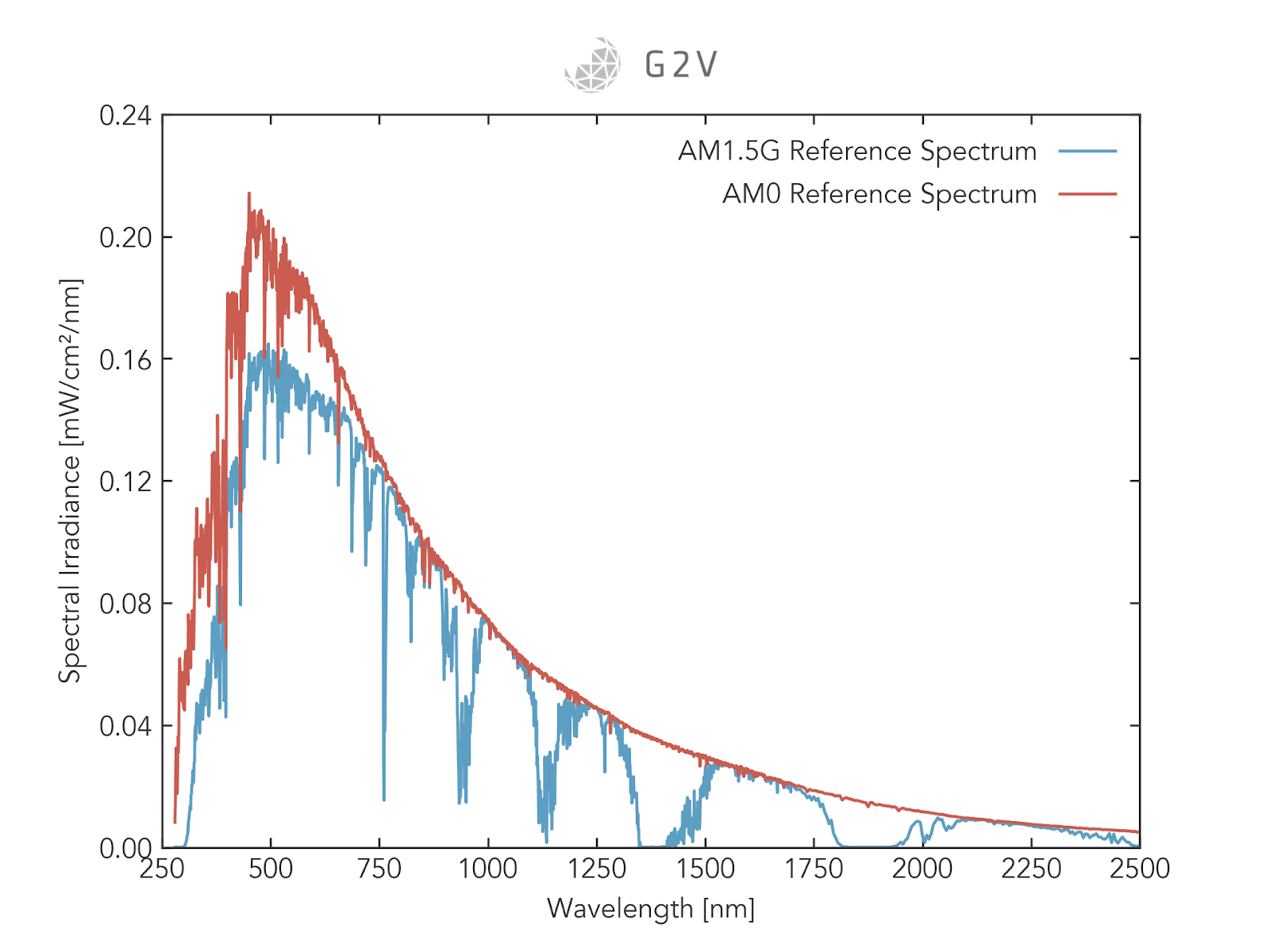
A plot of the two most common reference solar spectra, AM0 (in outer space) and AM1.5G
Power budgeting is particularly important for outer space applications, where the ability to refuel or restore spent power is challenging if not impossible. A solar cell’s overall efficiency depends on the incident spectrum. Therefore, if you’re making a solar panel for a Mars rover, it is recommended you test it under Martian sunlight.
If your photovoltaics are going even farther — say, toward the orbits of other stars — then the spectral content could be dramatically different. Below are some sample spectra of main-sequence stars. If your aerospace application primarily relates to one of these, you’re much better off testing with an appropriate spectral match rather than the standard AM1.5G.
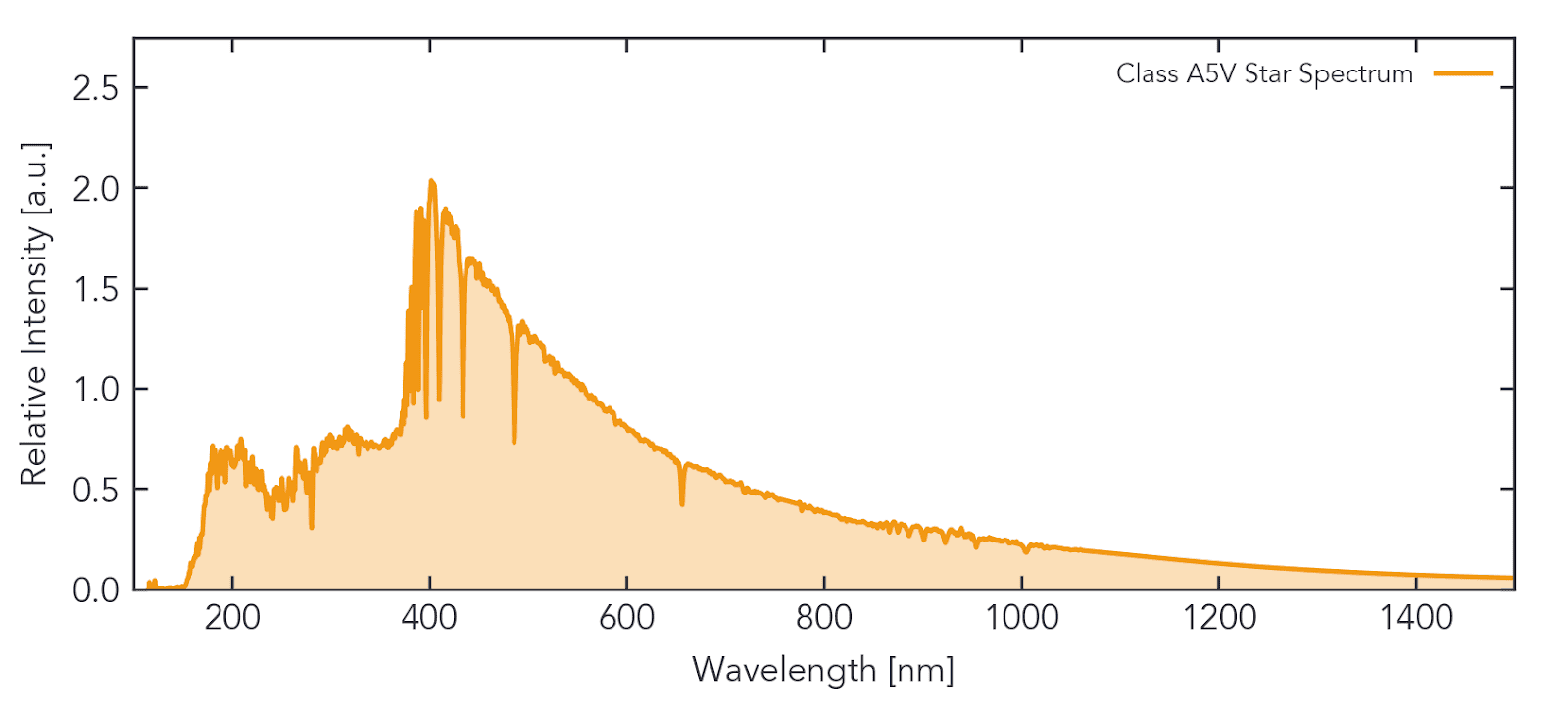
A sample A5V-class star spectrum from ESO data.
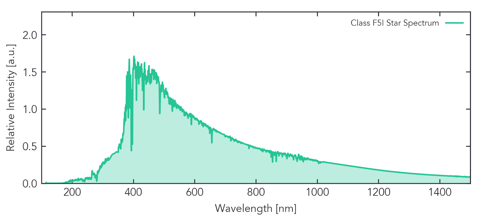
A sample F5I star spectrum from ESO data
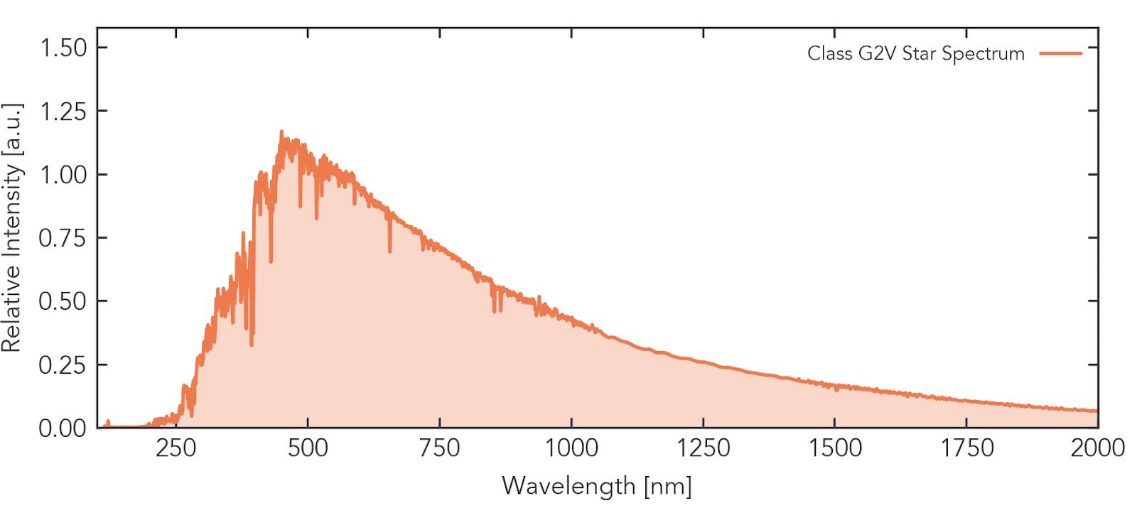
A sample G2V-class star spectrum from ESO data.
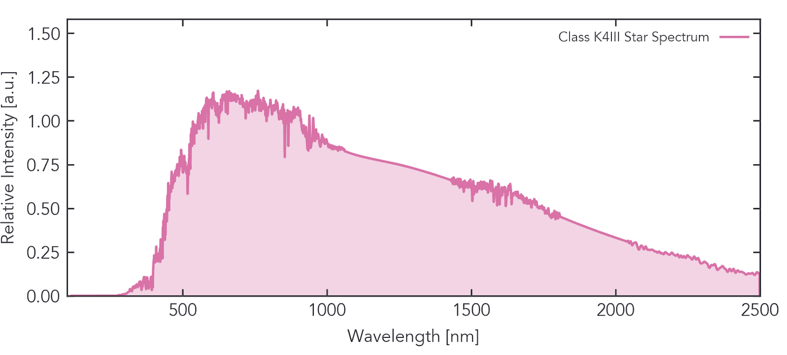
A sample K4III-class star spectrum from ESO data.
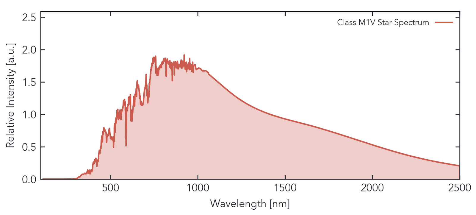
A sample M1V-class star spectrum from ESO data
Probing the Full Capabilities of Multi-Junction Cells
Multi-junction solar cells are of particular interest in aerospace applications, because of the broader spectral content in space due to the lack of atmospheric absorption. Each junction in these devices adds a new spectral wave band with the goal of absorbing more of the sun’s incident light. The layered stacks or tandem junctions have different material properties, requiring separate optimization and characterization under a solar simulator.
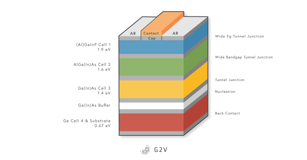
An example of the layer stack in a multi-junction solar cell. Image modified from source: https://pdfs.semanticscholar.org/e528/e2d097e6df1dcfbe5c4ef09c28fd123a12ef.pdf
In order to properly assess multi-junction cells, researchers have to bias the entire device with the background spectrum all the junctions will see, to ensure the background carrier densities are accurate. They then have to adjust the particular waveband of interest for each junction, measuring responsivity and quantum efficiency along the way. To achieve this adjustment means having a solar simulator where one can adjust specific spectral bands of interest.
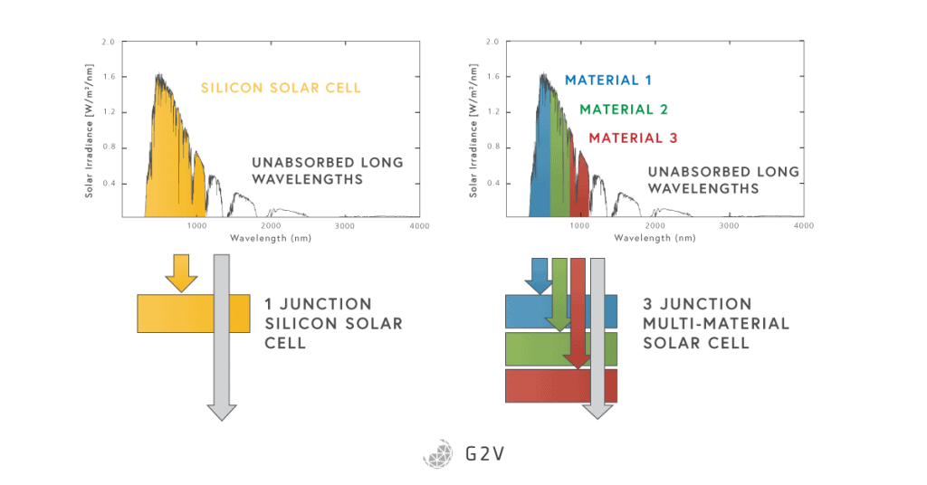
A comparison of the absorption of a single junction solar cell versus a multi-junction solar cell.
The National Renewable Energies Laboratory (NREL) is a world leader in testing and validating photovoltaic device performance. For their multi-junction test setup, they engineered an incredibly large, complex setup known as the One-Sun Multi-Source Simulator (OSMSS).
Starting from two 1500-W xenon lamps and two 750-W tungsten lamps, the OSMSS splits the output light into nine wavelength bands as shown below. A complex set of beam splitters, diffraction gratings and adjustable apertures couples the light into separate fiber optic bundles that are then combined before being put through the optics that achieve beam homogenization and collimation.
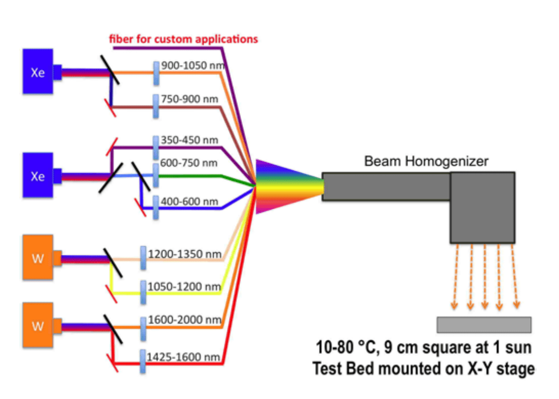
Schematic of NREL’s OSMSS system, which illustrates the complex setup they required to achieve the spectral tunability needed for testing multi-junction solar cells with traditional gas-discharge lamps. Image source: https://www.nrel.gov/docs/fy12osti/54134.pdf
The entire setup of the solar simulator is several times larger than the sample illumination area of 10 cm x 10 cm, as you tell from the image below, where the sample area and vertical adjustment motor are on the right, and the solar simulator control hardware are on the left, with a fraction of the optical instrument box shown.
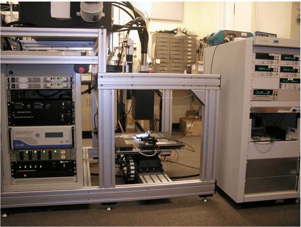
NREL’s OSMSS occupies a large volume relative to the illumination area it provides. Image source: https://www.nrel.gov/docs/fy17osti/66873.pdf
This complexity was needed in order to achieve the high-tunability necessary for characterizing multi-junction solar cells. For more information on the algorithms and methodologies involved in multi-junction solar cell validation, we encourage readers to look at NREL’s article here.
This example illustrates how complex and specialized solar simulators can be in order to meet the testing needs for one aerospace PV application (multijunction solar cells). There are some general principles for specifying and selecting a solar simulator for any given application, but below we’ll discuss the more general features that are useful for aerospace PV testing.
Solar Simulator Features that are Good for Aerospace PV
There will be advantages and disadvantages to any solar simulation technology, but some features are particularly important for aerospace PV.
Spectral Tunability for Multi-junction Solar Cell Testing
In NREL’s OSMSS system described earlier, we touched on one key solar simulator feature that is highly valuable for aerospace photovoltaic testing: spectral tunability. Because so many aerospace PV modules are using multi-junction cells to capture more of the sun’s energy, spectral tunability is more needed in this application to properly characterize all of the sub-junction behaviours, and ensure accurate background carrier densities.
This spectral tunability can be achieved in a few ways. Earlier we saw that NREL achieved spectral tunability using gas-discharge lamps and a complex system of optics and fiber bundles. That is definitely one approach, but their custom system is unique to their facility and hasn’t, to our knowledge, been replicated commercially. A common alternative to the NREL approach is to use different glass filters, but this requires a different glass filter for every desired spectral output. This can be impractical in situations where one doesn’t know the exact spectral output needed to probe a sub-junction, and needs an iterative set of varied filters to make incremental adjustments.
Another approach to spectral tunability is to use an LED solar simulator, and this is in fact the solution NREL began investigating through G2V Optics’ Sunbrick. LED solar simulators build their output spectra by combining the outputs of several different LED sources, which makes the ability to tune specific spectral regions very feasible. The caveats are that the LED solar simulator’s electrical hardware must be designed with this flexibility, and the LED bandwidths must be sufficiently narrow for the spectral regions of interest. Because multi-junction solar cells usually have sub-junction responsivity bandwidths on the order of 100 nm, tunability via LEDs is usually viable, as shown in the figures below.
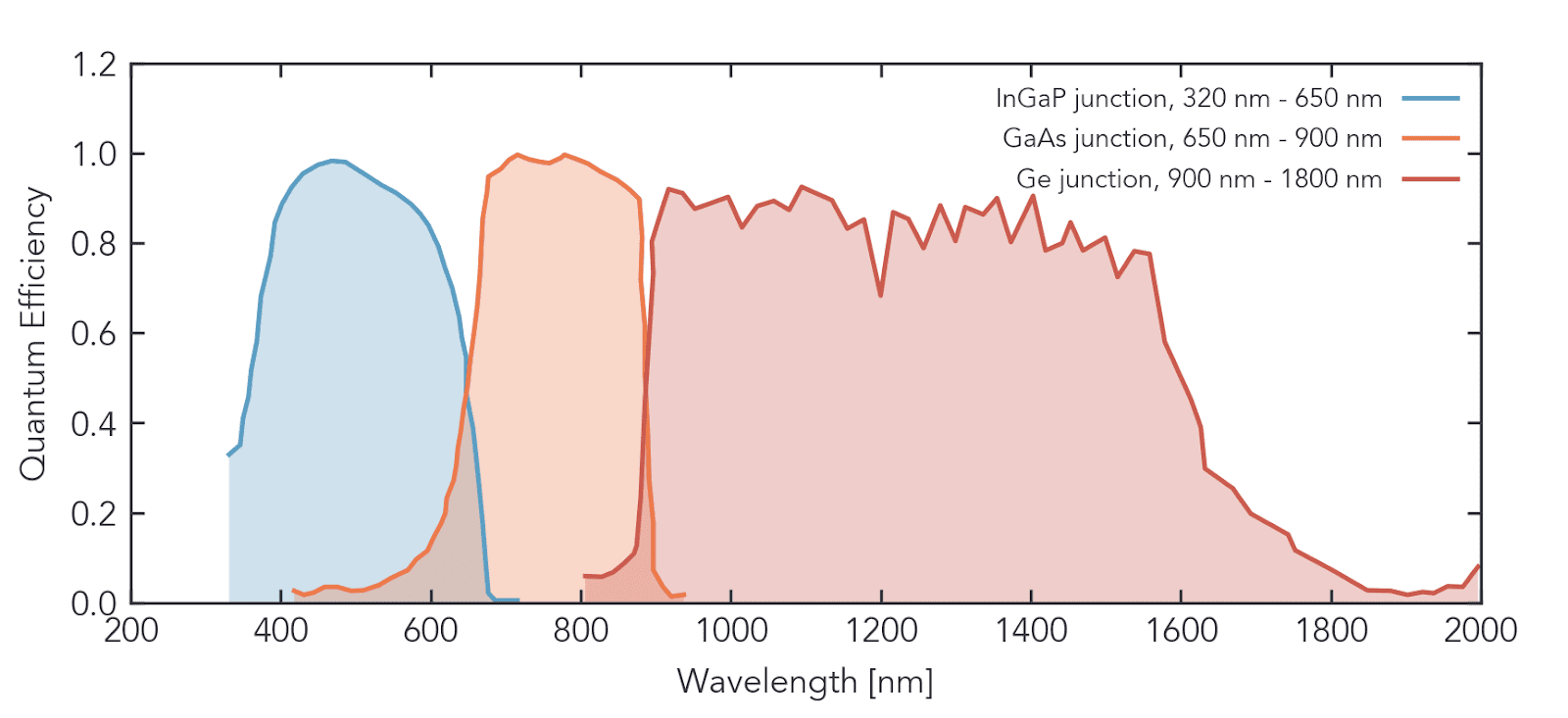
The quantum efficiencies of different sub-junctions in a typical multijunction cell, showing wide spectral coverage by combining multiple spectral bins 200 nm wide or larger. Data source: https://doi.org/10.1117/12.559734
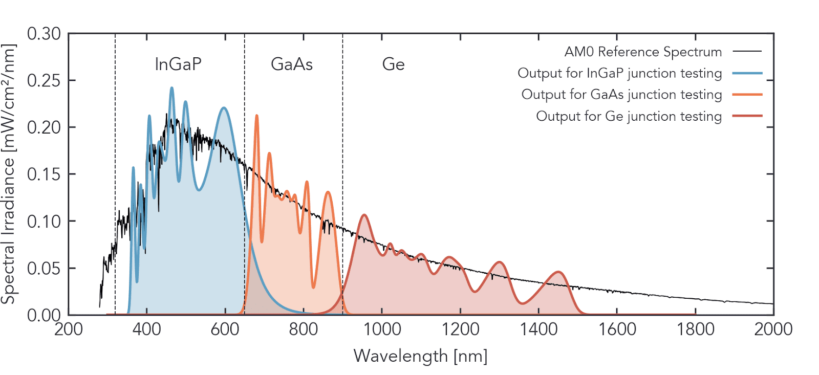
Example of different spectral outputs from G2V’s Sunbrick product line, demonstrating the suitability of LED solar simulators for testing specific sub-junctions of multi-junction solar cells.
LED solar simulators usually require far less, or much smaller optical hardware than the NREL OSMSS example discussed above, which means that a tunable LED solar simulator likely has a smaller footprint than its traditional gas discharge lamp-based counterpart for this type of high-tuning application.
“It feels like moving from an old-school CRT TV to flat screen technology. We have this massive volume of instrumentation for our old solar simulator, and in front of it sits [an LED solar simulator], tiny by comparison, but nominally able to achieve the same or better results.”
Extraterrestrial AM0 and Other Output Spectra
Closely related to spectral tunability is the ability for a solar simulator to output different solar spectra. Unlike most photovoltaic applications, aerospace solar cells will perform under much different conditions than the standard AM1.5G spectrum. While that’s true of any solar cell (because of sunrise, sunset and cloud conditions) the difference is more profound when going from AM1.5G to AM0 (the spectrum in outer space). Having a solar simulator that can accurately produce the primary expected spectra is an important feature to seek.
Traditional gas-discharge lamp-based solar simulators achieve different output spectra using glass filters. With this approach, a different glass filter is required for every desired output spectrum. Unfortunately, even if one has the correct glass filter, it is subject to deterioration (darkening) which reduces a filter’s usable lifetime for consistent spectral output.
LED solar simulators can produce different spectra provided they have sufficient LEDs in the spectral regions of interest.
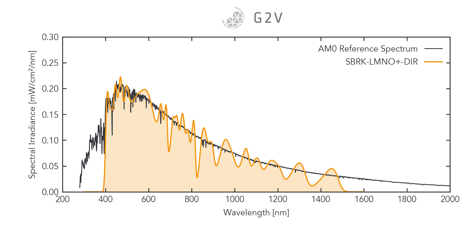
An example AM0 spectral output of an LED solar simulator (the G2V Sunbrick) compared to the AM0 reference spectrum.
The main limitations with LED solar simulators for providing different output spectra are whether or not the electrical hardware supports these intensity adjustments, and whether or not the LEDs have sufficient output fluxes to produce the higher-intensity AM0 spectrum.
For a closer comparison of spectra from different solar simulator manufacturers, please see our article on the IEC 60904-9 solar simulation standard.
Wider Spectral Output Radiation Testing
Because aerospace photovoltaic cells are increasingly likely to use wider spectral regions than traditional silicon solar cells, the solar simulator used to test them must also output a broader spectrum. The historical spectral range of 400 nm to 1100 nm for the AM1.5G spectrum may not be sufficient to test the full breadth of an aerospace solar cell’s capabilities. Multi-junction solar cells may broaden the spectral range to as wide as 300 nm to 1800 nm, depending on the sub-junctions used.
Because traditional gas-discharge lamps emit blackbody radiation, their spectral range extends considerably into the infrared to meet this need. One caution for users, however, is that gas-discharge lamps have sharp gas emission lines that need to be filtered out, and their infrared output is usually higher than the sun’s spectrum, which also needs to be filtered and managed. Despite these limitations, gas-discharge lamps can output reasonable spectra in the range of 300 nm to 2000 nm.
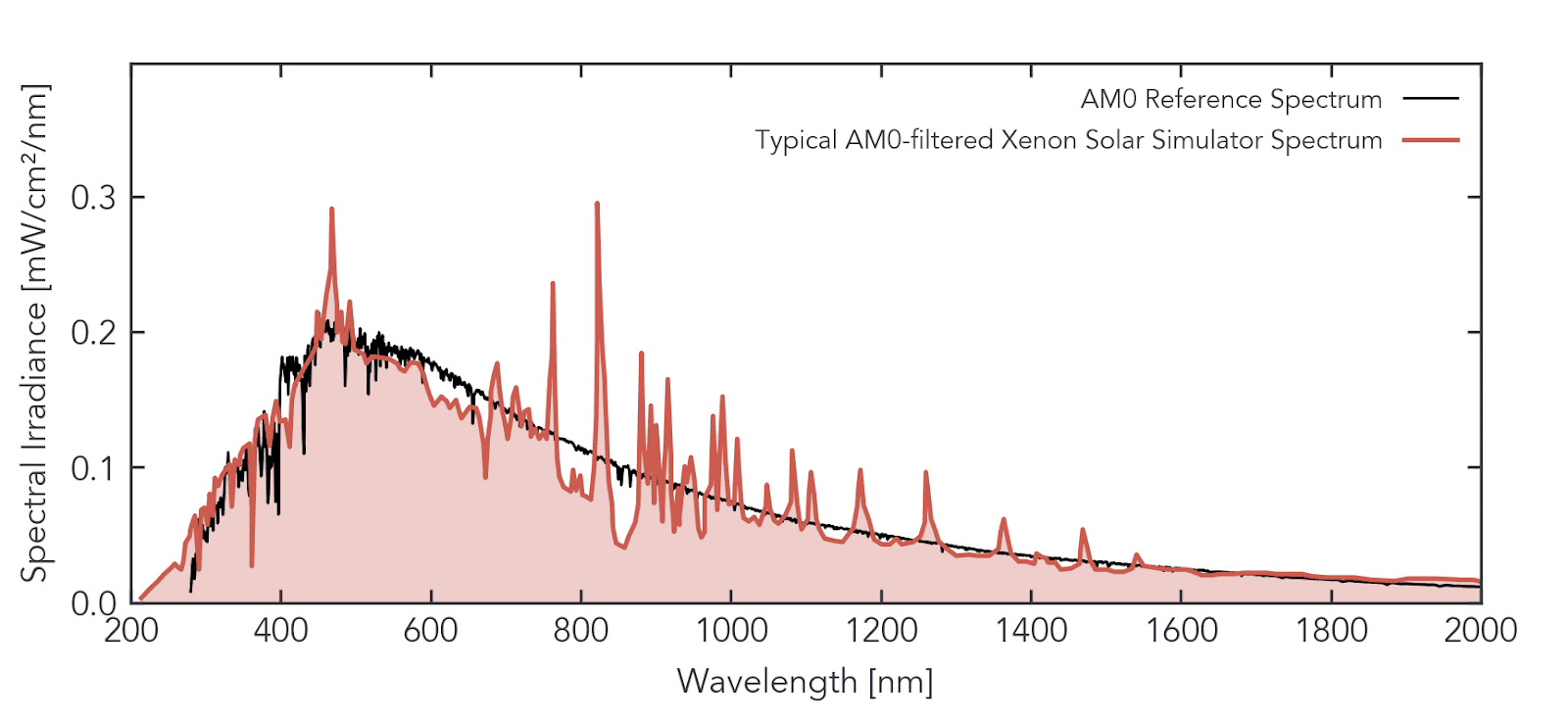
The typical output of a xenon arc lamp solar simulator, after passing through a glass filter designed for AM0. Data source. https://www.researchgate.net/publication/231032910_A_wide-beam_continuous_solar_simulator_for_simulating_the_solar_flux_at_the_orbit_of_Mercury.
LED solar simulators are at a bit of a disadvantage in this regard, because commercial LEDs only reach about 1500 nm. However, LED material technology continues to develop, and more viable material solutions continue to be released, with solutions out to 1800 nm on the horizon. This is of course a moot point if your device under test only responds to wavelengths below 1500 nm.
Both UV LEDs and IR LEDs remain somewhat costly, making them a potentially more expensive option up front. However, we encourage prospective solar simulator buyers to consider the full breadth of characteristics and lifetime costs for solar simulator ownership, which we discuss in detail in our article here.
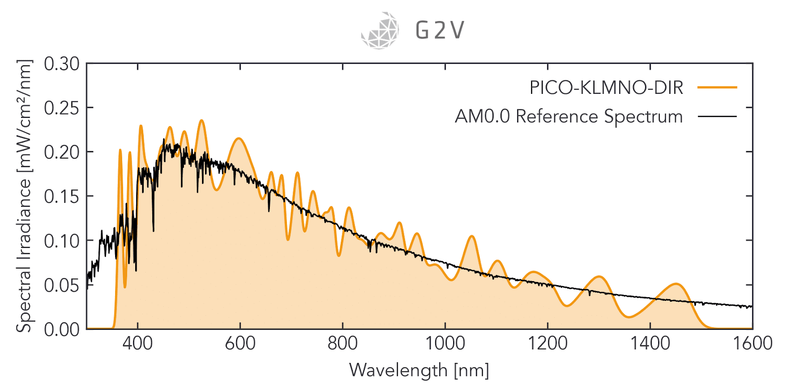
An example AM0 spectral output of an LED solar simulator (the G2V Pico) demonstrating spectral output from 350 nm 1500 nm. This spectral range can be wide enough for many applications.
Programmable or Scheduled Spectral Outputs for Aerospace PV Module Testing
The range of spectra experienced by an aerospace PV module might be so unique and different from a traditional ground-based solar cell that a user wants to test the overall performance and degradation after cyclic sun exposure. Under such circumstances, having a solar simulator that can vary its output programmatically based on a user-defined schedule is advantageous. This feature might be implemented via the existing software/hardware on the solar simulator, or need some additional setup by using an API.
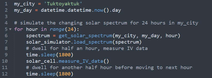
A hypothetical example of Python code being used to control a solar simulator. In this case it is cycling through 24 hours and reproducing the spectrum at Tuktoyaktuk on the current day, measuring the IV data every hour.
Some of the same technological constraints affecting spectral tunability (discussed above) also influence whether or not the output spectrum can be programmed. However, one feature is not a guarantee of the other, so be sure to investigate this aspect of any potential solar simulator if you anticipate a need for it in your testing.
Integrated IV Testing Modules
One useful feature or add-on that many solar simulators offer is an IV testing setup. For obvious reasons, this can be advantageous to aerospace PV applications. Since the IV test setup is designed to work well with the original solar simulator, this can be a good strategy to streamline the process of validating the current (I) and voltage (V) parameters of a solar cell.
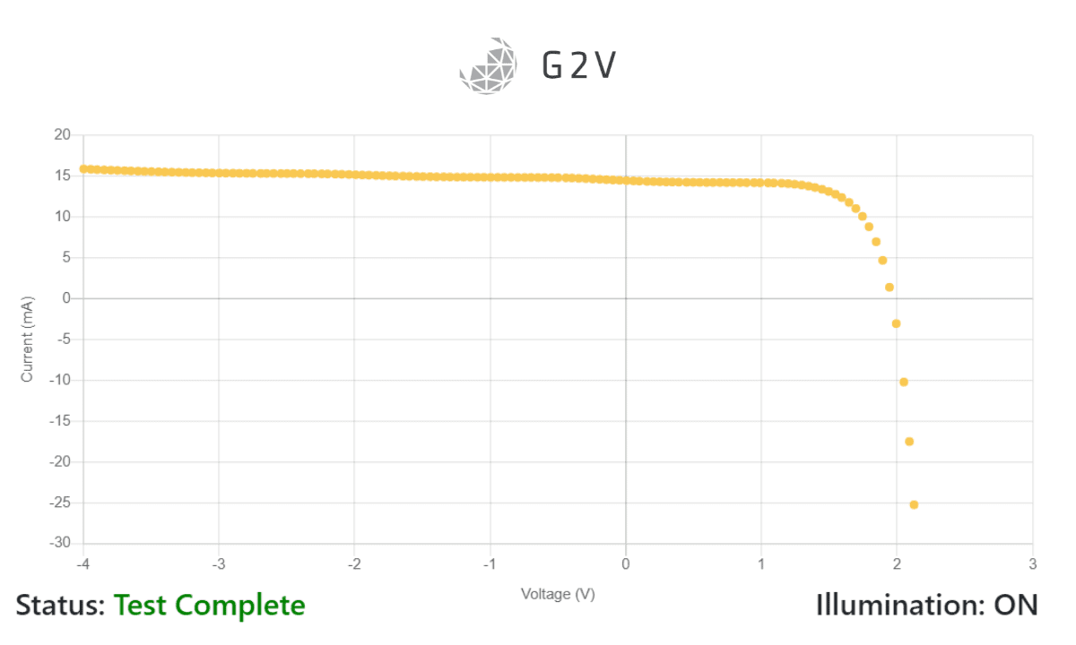
A sample set of test results using G2V’s IV module for the Pico solar simulator product line.
The suitability and capabilities of IV testing modules offered by solar simulator manufacturers vary, so it’s best to evaluate them individually based on the needs of your particular solar cells. For example, the IV testing modules may or may not accommodate multi-junction probing, and they may or may not include a temperature control stage for ensuring stable sample temperatures during testing.
Flash Capabilities of a Solar Simulator
The performance characteristics of any solar cell vary with temperature, and so it is an important parameter to either control or quantify during aerospace PV testing. Any steady-state (i.e. constant or continuous illumination) solar simulator will introduce heating of the device under test (DUT) to some extent, and so this excess heat must be managed. One way to manage the excess heat is to temperature-control the DUT, but this can be impractical for production lines or experimental cells. Another common way to manage the excess heat is by using a flashing solar simulator.
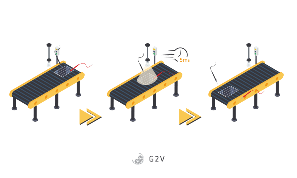
In illustration of a flashing solar simulator being used in a solar cell production line. Not only does the short-duration flash minimize heating, but it is suitable for this type of rapid-throughput environment.
Flashing solar simulators aim to shine light on a solar cell via an output pulse that is:
- Long enough in duration to allow the gathering of the full set of current-voltage (IV) data for the DUT;
- Long enough in duration for the gathered IV data to be independent of any capacitance effects from the solar cell, and;
- Short enough in duration to avoid any appreciable heating of the DUT.
For more information about flashing solar simulators, please see our comprehensive solar simulation article here. The key aspects to investigate for a flashing solar simulator are:
- pulse duration – make sure it’s long enough for your IV data capture
- stability of the spectrum over that pulse – make sure the spectral match remains Class A or better throughout the pulse
- properly synchronized IV data capture with the flash – to ensure that you’re capturing the solar cell’s response to the desired spectrum.
Of course, it’s also important to ensure that all of the other testing aspects we’ve discussed above hold true for the pulsed output conditions. If you are interested in a pulsed or flashing solar simulator, we’d love to hear from you.
Summary: Enhancing Photovoltaic testing for Aerospace
Solar simulators were originally specified for Earth-based photovoltaic cell testing, but they are nevertheless capable of reproducing sunlight under a variety of aerospace-relevant conditions.
New technologies have incorporated features that can greatly facilitate testing and ensure confident ground-validation of an aerospace solar cell’s behaviour in flight.
The key characteristics to consider in a solar simulator intended for aerospace PV testing are as follows:
- Spectral Tunability – if you need to probe the sub-junctions of a multi-junction solar cell, tunability is essential. LED solar simulators do this more easily than traditional bulbs.
- AM0 and other spectra – getting a solar simulator that can produce the spectra your PV cell will experience on Earth or in space will give you reliable performance estimates.
- Wide spectral output – the wider spectrum received in aerospace applications means you may need to get a solar simulator with a wider spectral output. Gas discharge lamps can usually output 300 nm – 2000 nm, while LEDs are more restricted to 350 nm – 1500 nm. No matter the spectrum, ensure the output retains a reasonable spectral match to your target spectrum.
- Programmable or scheduled outputs – if it’s important to test the impact or performance degradation after repeated exposure to fluctuating sunlight, a programmable output spectrum can produce more accurate results.
- Integrated IV testing modules – depending on your PV testing needs, a solar simulator manufacturer’s optional or integrated IV test modules might allow you to get an instrument and measurement system that streamlines your work.
- Flash capabilities – in order to minimize the excess DUT heating introduced by a solar simulator’s illumination, you may want to consider using a flashed light source. If you are interested in a pulsed or flashing solar simulator, we’d love to hear from you.
References
ASTM (2012). ASTM G173-03(2012): Standard Tables for Reference Solar Spectral Irradiances: Direct Normal and Hemispherical on 37° Tilted Surface. ASTM International. https://www.astm.org/g0173-03r12.html
Cotal, H.L., Fetzer, C.M., Boisvert, J.C., Kinsey, G.S., King, R.R., Hebert, P., Yoon, H., & Karam, N.H. (2009). III–V multijunction solar cells for concentrating photovoltaics. Energy and Environmental Science, 2, 174-192. https://doi.org/10.1039/B809257E
Dimroth, F., Baur, C., Bett, A.W., Meusel, M. and Strobl, G. (2005). 3-6 junction photovoltaic cells for space and terrestrial concentrator applications. Conference Record of the Thirty-first IEEE Photovoltaic Specialists Conference, pp. 525-529, doi: 10.1109/PVSC.2005.1488185. https://doi.org/10.1109/PVSC.2005.1488185
Emery, K. (2016). Photovoltaic Calibrations at the National Renewable Energy Laboratory and Uncertainty Analysis Following the ISO 17025 Guidelines. Technical Report. Web. https://www.nrel.gov/docs/fy17osti/66873.pdf
Erickson, K. (2022). What Powers a Spacecraft? NASA Science Space Place. https://spaceplace.nasa.gov/what-powers-a-spacecraft/en/
Jin, J., Hao, Y. and Jin, H. (2018). A universal solar simulator for focused and quasi-collimated beams. Applied Energy 235, pp. 1266-1276,ISSN 0306-2619. https://doi.org/10.1016/j.apenergy.2018.09.223
Moriarty, T., Jablonski, J., and Emery, K. (2012). Algorithm for building a spectrum for NREL’s One-Sun Multi-Source Simulator. 38th IEEE Photovoltaic Specialists Conference, pp. 001291-001295, doi: 10.1109/PVSC.2012.6317838. https://doi.org/10.1109/PVSC.2012.6317838
NREL (2022). National Renewable Energy Laboratory. U.S. Department of Energy. Web. https://www.nrel.gov/index.html
Pickles, A. J. (1998). A Stellar Spectral Flux Library: 1150–25000 Å. Publications of the Astronomical Society of the Pacific, 110(749), 863–878. https://doi.org/10.1086/316197
Data downloaded from ESO library at https://www.eso.org/sci/facilities/paranal/decommissioned/isaac/tools/lib.html
Summhammer, J. (2013). Short flash and constant load PV-module tester. IECON 2013 – 39th Annual Conference of the IEEE Industrial Electronics Society,, pp. 8116-8120, doi: 10.1109/IECON.2013.6700490. https://doi.org/10.1109/IECON.2013.6700490
Thomas, N, Beck, T, Chakraborty, S, Gerber, M, Graf, S, Piazza, D, & Roethlisberger, G (2011). A wide-beam continuous solar simulator for simulating the solar flux at the orbit of Mercury. Measurement Science and Technology, 22(6), 11. doi:101088/0957-0233/22/6/065903 https://doi.org/10.1088/0957-0233/22/6/065903
Warner, J.H., Walters, R.J., Messenger, S.R., Lorentzen, J.R., Summers, G.P., Coral, H.L., and Karam, N.H. (2004). Measurement and characterization of triple junction solar cells using a close matched multizone solar simulator. Proc. SPIE 5520, Organic Photovoltaics V. https://doi.org/10.1117/12.559734